

Enclosed multi-pole conductor systems (up to 200 Amp)
Overview
Technical Data
Components
Downloads
Overview
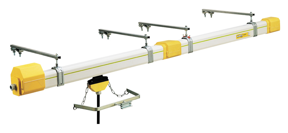
High Security and user protection
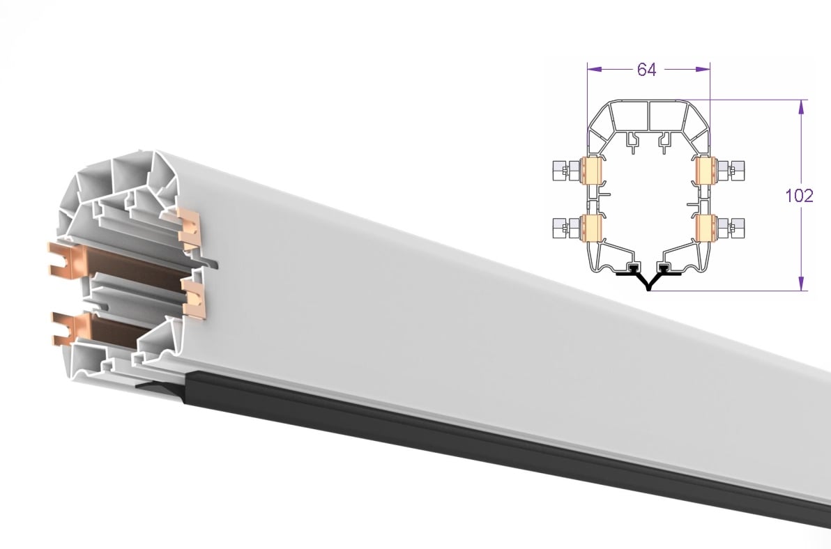
The closed profile of the IP23 rail guarantee the user against electric shock even under the rain: all the accessories ensure the IP23.
Quick installation:
Multiple pole lines with 4 or 5 pre-mounted conductors and many accessories to clip-on (no tools required)
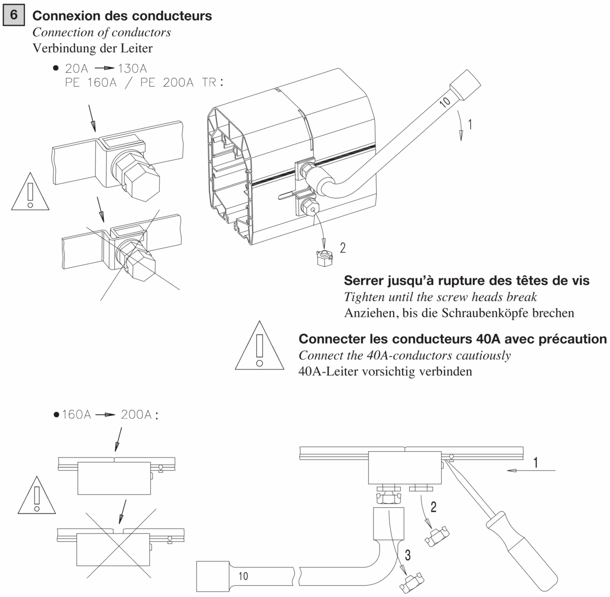
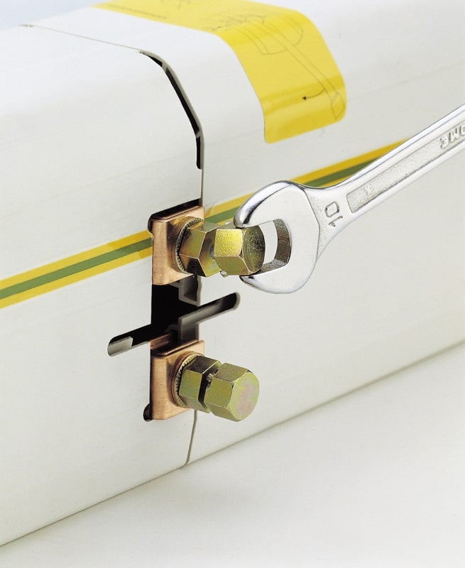
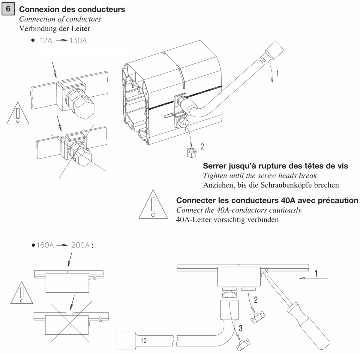
Quick and easy connection:
Connection system with built-in self-breaking screws, guaranteeing tightening at optimum torque
Reduced voltage drop at connections:
The very large exchange surface, and tightening maintained at optimum torque allow reducing and controlling voltage drop
Excellent operator safety and protection:
The closed profile of the mounted line with the full set of accessories has a protection level of IP23, which means that the equipment is protected so that people cannot access the dangerous sections, even under the rain
Operation reliability:
The current collectors, tested against requirements stricter than the standards, are designed to run for several thousand kilometers, providing reduced maintenance of facilities
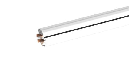
Details of profile
Number of poles: 4 or 5
Intensity: 12A, 20A, 40A, 60A, 100A, 130A, 160A, 200A
Maximum operating voltage: 750 V
Outstanding advantages
- Self-extinguishing closed PVC profile, of modern design
- Easy and quick mounting of the line in its suspensions
- Quick and reliable connection
- No preparation required
- Increased safety
- Modular and interchangeable
Standards
- Protection level IP23 according to EN60529
- Meets the requirements of Standards EN60439-2, CEI61439-6 and EN60204-32
Special elements available
- Transfer elements
- Curves
- Circuit interruption elements
- Inlet gates
- Ventilation elements
- Switching fingers
- Expansion joints
- Special trolleys and carriers
- Data transfer…
Guarantee
Our equipment is guaranteed one year against any material or manufacturing defect recognized by ourselves. As we are not responsible for its installation and operation, our guarantee covers only replacement or repair (at our own choosing) of the part recognized to be defective.
We do not accept responsibility for any defects arising from faulty supervision or maintenance. We also disclaim liability for any production stoppages that may result. Any arbitration shall be held in Strasbourg, even when several defendants are involved.
Technical Data
High Security and user protection
The closed profile of the IP23 rail guarantee the user against electric shock even under the rain: all the accessories ensure the IP23.
See related sections for special items
1. Applications
The electrical supply rails with mobile socket are generally used for the electrification of travelling cranes, cranes and hoists, narrow-aisle stores, work station equipment (tasksaver systems), elements of electric hoisting equipment, theater stages, sewage treatment and composting equipment, and other diverse applications, inside and outside.
2. General technical data:
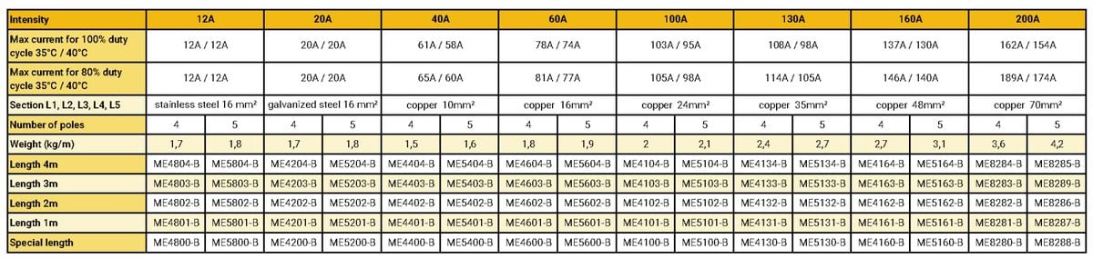
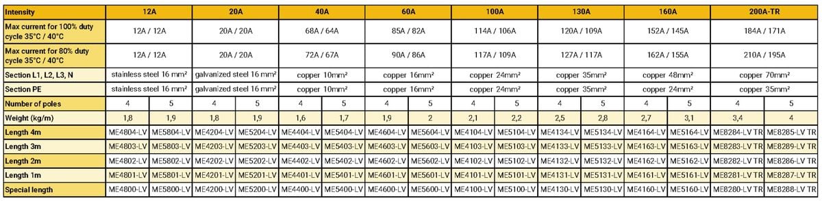
Rated operational intensity:
The MOBILIS ELITE lines are available in several intensities 20 A, 40 A, 60 A, 100 A, 130 A, 160 A and 200 A.
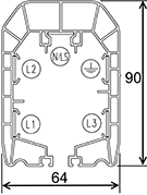
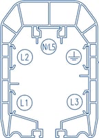
Number of poles:
The MOBILIS ELITE lines are available in 4-pole or 5-pole version.
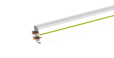
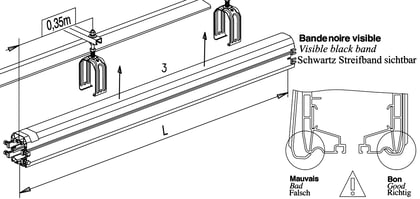
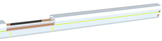
The ground conductor (PE) is marked on the line by a green-yellow band.
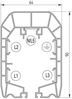
The neutral conductor (N), when present, is located in the top section of the casing.
The phases (L1, L2 and L3) are located as shown on the diagram opposite.
Rated operational and insulation voltage:
750 V alternative, 50 Hz for standard version
440 V alternative, 50 Hz for high-temperature version
Temperature of use:
–30°C to +55°C in the standard version, –30°C to +75°C in the high temperature version
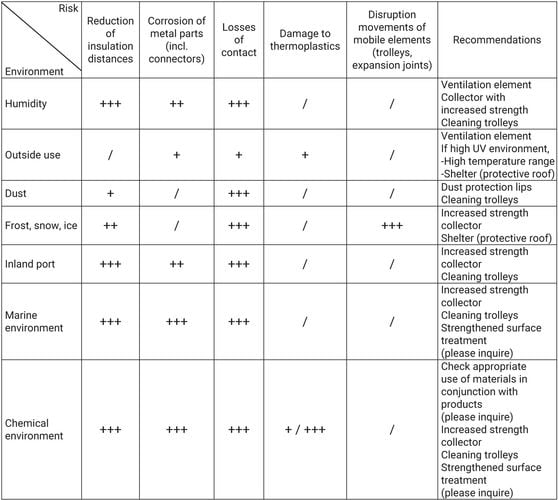
3. Environment:
Category 3 of ISO 2081 (outside mild), inside, outside use under rain or dust. A version with 600h resistance under saline mist is available. Please inquire.
Inside | Outside | Dust(1) | With snow
Low Temperatures(1) | Rain

(1) With protective lips for dust and special trolley for low temperatures
The Mobilis Elite feeding system is exclusively designed to run with opening of the casing facing downwards.
Validate suitability of the product to run in unfavorable environmental conditions (e.g. humid air flow, steam, frost…).
An unfavorable environment brings the following risks:
Key
- +++ High risks
- ++ Moderate risks
- + Low risks
4. Applicable standards:
The Mobilis Elite range has been designed to meet Standards EN60439-2, EN60204-32 and CEI61439-6. It bears the CE marking.
5. Protection index:
A mounted line with the full set of accessories has a protection level of IP23 according to EN60529, with no lips or with dust protection lips.
Caution: If one accessory is removed, the level of protection is eliminated.
IP2X means that the equipment is protected so that people cannot access the dangerous sections, i.e. it is impossible to introduce a standard test finger of Ø12 mm with an effort of 10 N. The equipment is also protected against solid foreign bodies, i.e. it is not possible to introduce a metal sphere of Ø12.5 mm with an effort of 30 N.
IPX3 means that the equipment is protected against rainwater falling at a maximum angle of 60° in relation to the vertical plane.
The Mobilis Elite range is designed for both inside and external use.
If a Mobilis Elite line is used in an area open to the public, additional safety measures should be installed (protection level IP4X required according to EN60204-32).
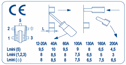
6. Insulation distances:
The insulation distance between conductors or between conductors and accessible parts:
– Distance in the air: 10 mm min.
– Creepage distance: 30 mm min. (according to EN60204-32)
7. Flame resistance:
All materials used to build Mobilis Elite lines are self-extinguishing; they pass successfully glowing/hot line tests under 960°C for elements in contact with live parts and V-0 according to UL-94.
8. Safety pins
Line: to prevent mounting errors, 2 line elements with consecutive intensities cannot be assembled on the same line.
Identification of ground conductor: The ground conductor (PE) is marked on the line with a green-yellow band.
The connecting points on the line and the collecting trolleys are marked.
Trolley: with the safety pin system, it is not possible to insert a trolley into the line incorrectly, leading to a phase-earth connection.
9. Space requirements:
In addition to the space required for the various components (see in this section), make provision for mounting/dismounting of electrical wiring.
10. Protection against forgetting:
Any connection, not fully established, prevents closing of covering flange, or of end-cap due to the self-breaking screws.
11. Operating life – endurance
The lines and accessories are built to withstand several years of use in a normal industrial environment. The current collectors are designed to run for several thousand kilometers (see the Maintenance section for recommended service schedule).
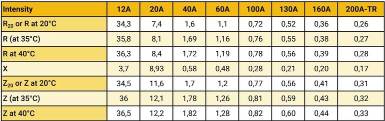
12. Resistance, reactance, and impedance under normal condition
Impulse running:
When the rush of current is of short duration followed by long rest periods, the figures in the table below can be used.
The value of the resistance R, reactance X and impedance Z at 50 Hz at ambient temperatures of 20°C and 35°C (short period current): the figures in the table are given in m?/m.
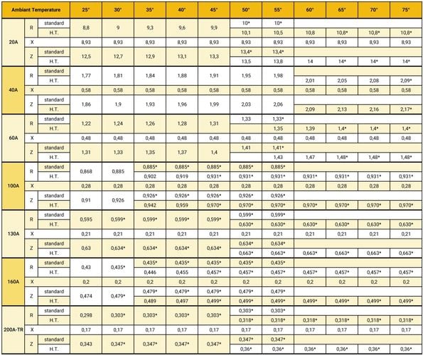
Intensive running:
The value of the resistance R, the reactance X and the impedance Z at 50 Hz according to the ambient temperature and taking into account the Joule effect for the different ratings carried by their nominal intensity and for a duty cycle as per paragraph below (* = Fm<100%).
The figures in the table should be multiplied by 10–3 to obtain ?/m:
13. Value of the resistance R and of the resistance X of fault loop
See EN60439-2 and CEI61439-6, below Ddata for the application of the impedance method:
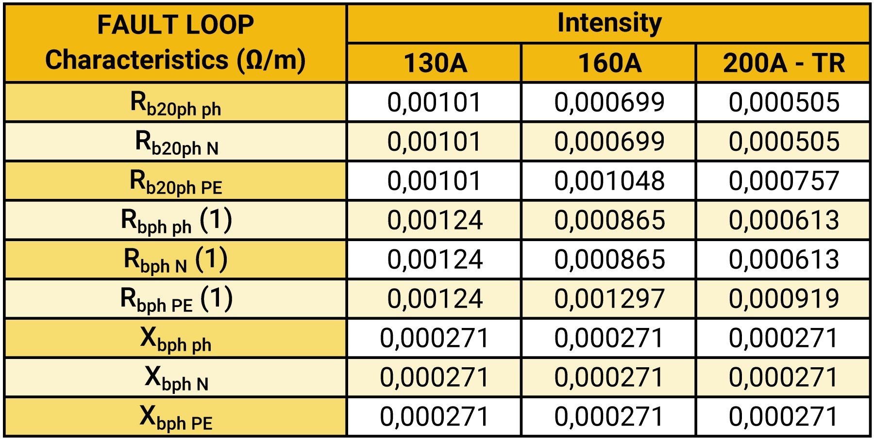
(1) at 35°C ambient temperature and maximal rated current.
Protection against short-circuits:
For intensities ?130A, Icw<10kA.
For intensities 160A and 200A TR: Ipk=11kA
14. Intensity according to duty cycle
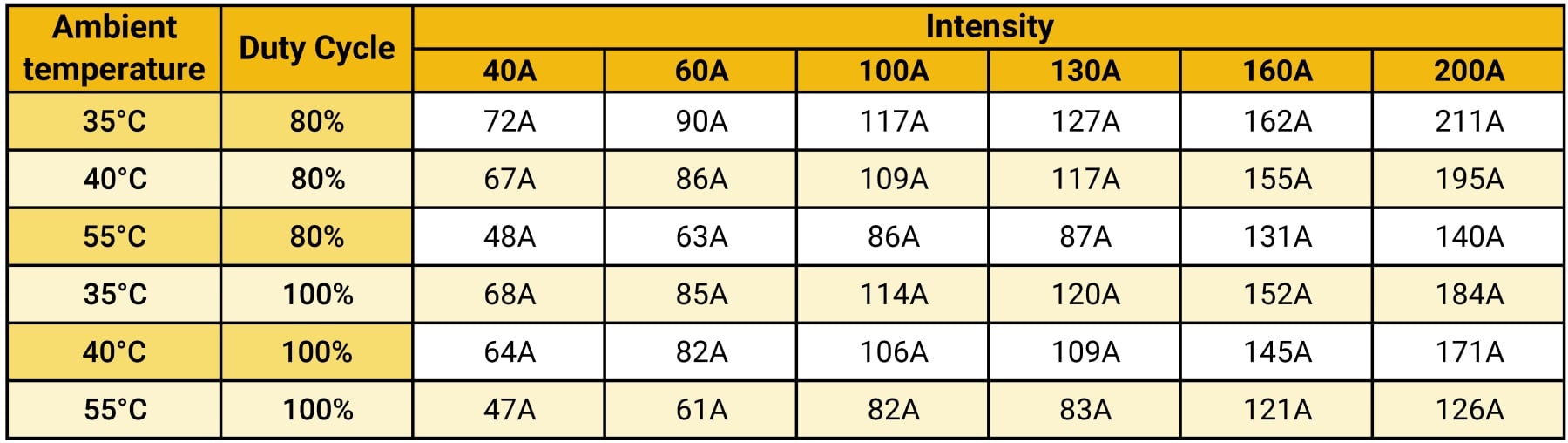
15. Downgrading according to temperature
You may use the Online calculation Tool to calculate the values according to the maximum temperature.
Or find out the maximum permissible duty cycle factor in the table below:
If, for a given intensity, Fm is higher than the value specified, it is necessary to select a higher intensity.
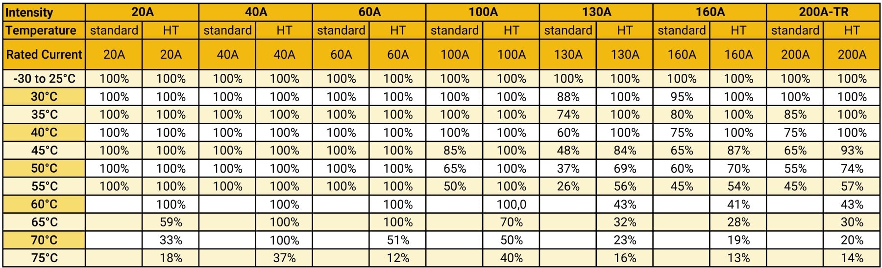
If not, refer to the following table for Elite 100% Duty Cycle Factor:
When the line carries a permanent current IN (duty cycle factor 100%), it may be necessary to downgrade the intensities according to the temperature.
If IG is the intensity of the rail and f is the correction factor defined in the table below, the new maximum permissible intensity Iadm will be:
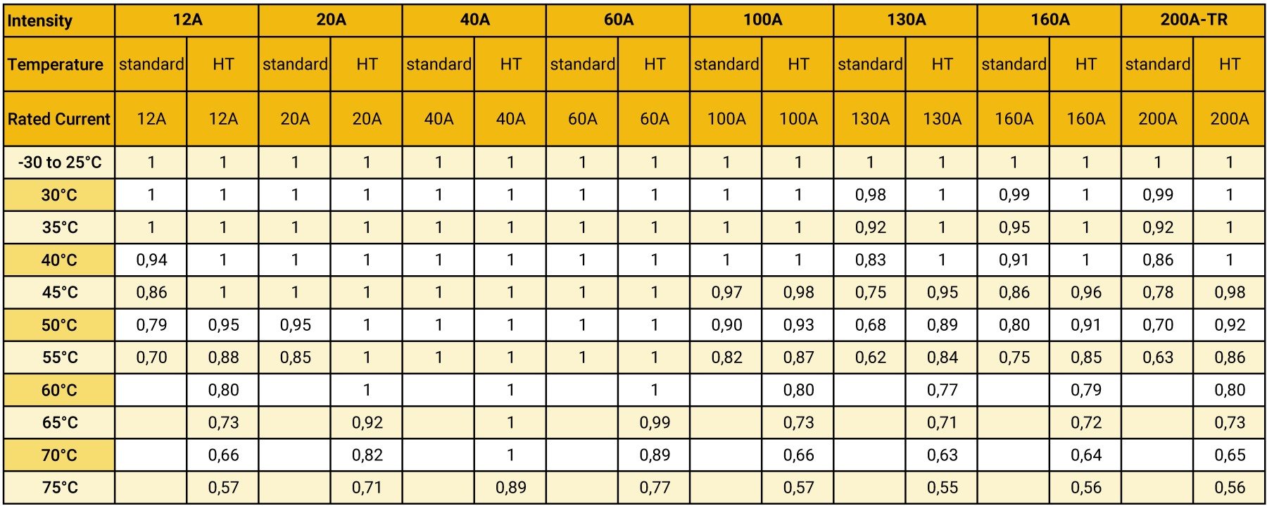
The intensity selected may be retained if the current in the line (IN) is lower than or equal to the permissible intensity (Iadm) :
IN ? Iadm
16. Components
See components section
(Straight elements, trolleys, feeding boxes…)
17. Assembly Instructions
See related section
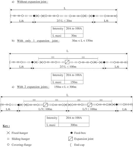
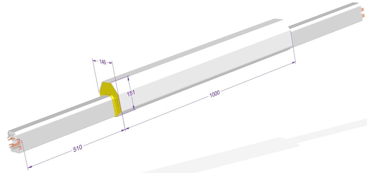
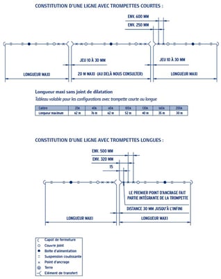
18. Special rules for striaght elements with rigid wiring
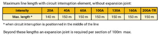
Reminder: Under normal conditions, no expansion joint is required for the installations according to the table below

However, in some cases the feeding boxes are connected with rigid cables preventing expansion, which should then be considered as anchoring points. If such is the case, the following rules shall apply.
Rules :
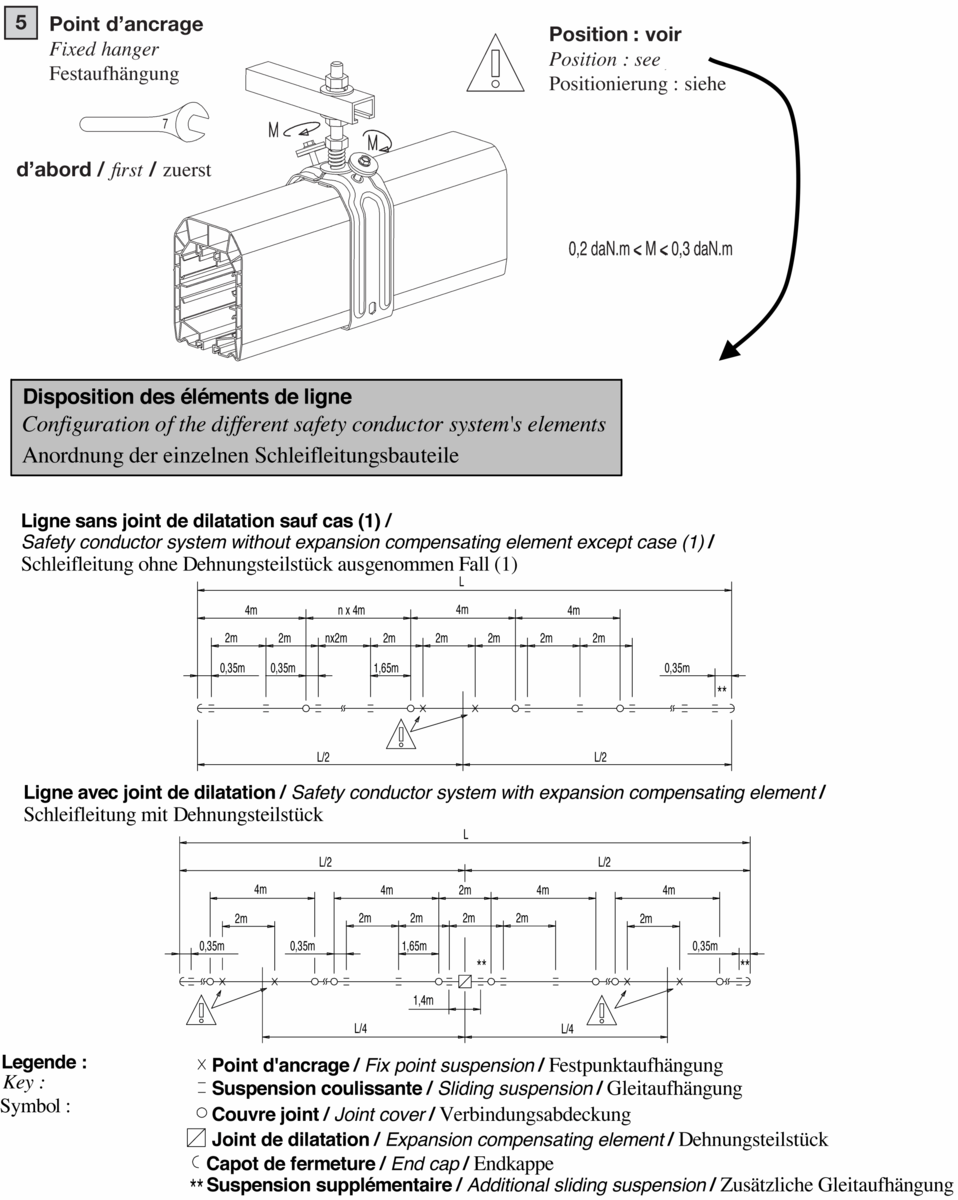
1. Placement of Fixed Hanger:
The anchoring points are to be located on the line element which is the closest to the connecting box.
If some highly rigid cables are used preventing expansion, the anchoring points shall be located close to line feeding:
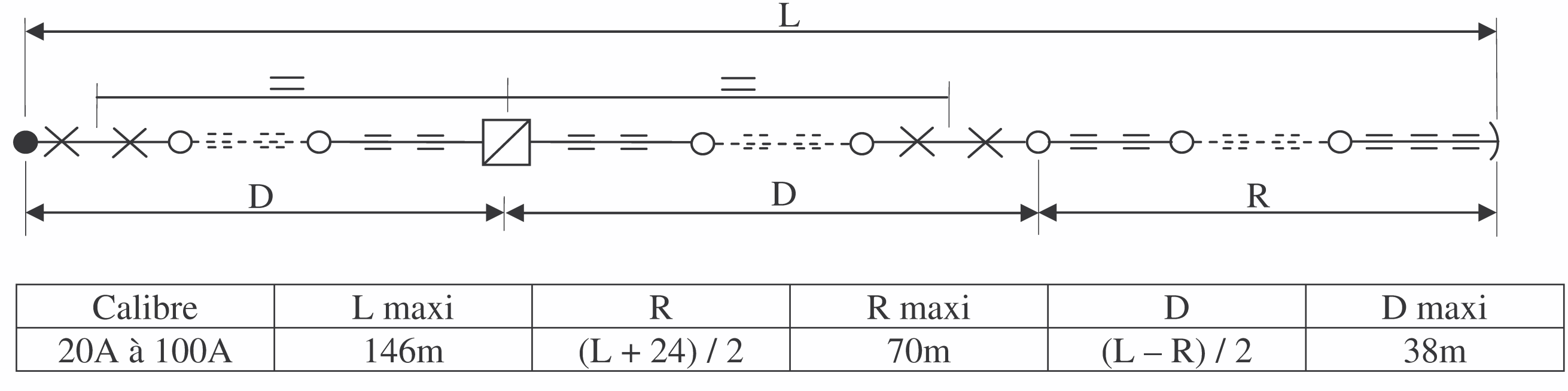
2. End-line Feeding with rigid cable
For lines longer than the lengths in the below table, an expansion joint will be required:

For the intensity 12A, the maximal length will be determined by the voltage drop for current higher than 3,5A (for weaker currents, please consult us)
If end-line feeding uses rigid cables and an expansion joint:
3. In-line feeding
When feeds with rigid cables are located close to the anchoring points, the standard rules apply. Otherwise, lengths without expansion joints are limited to 30m for in-line feeds between two anchoring points. Beyond this, an expansion joint is required:
19. General maintenance:
1) General points
Any intervention must be carried out with the line switched off at the mains.
Maintenance primarily concerns the conductive tracks and the trolleys.
Any damage to the conductive tracks will reduce the operating life of the brushes.
This damage may take different forms:
– Oxidation due to a chemical environment
– Abrasive dust
– Damage due to electrical arcs in the case of a faulty contact following oxidation, heavy soiling or use of worn brushes.
Regular inspection is required to check the wear of the brushes, casters of wheels and the quality of the conductive tracks according to the rate of use, the distance covered, and the chemical environment. Inspection is required when the distance covered reaches 3,000 km or after one year of use at the most.
2) Track Monitoring
The tracks normally become covered with a protective black sheen with the repeated passage of the collector trolleys with Elite. Check the surface condition of the tracks at a junction point between the casings. The surface should be smooth. If the tracks are rough to the touch, run the cleaning trolley. You will find them under the components section.
Caution : the cleaning trolley is not designed to run over long distances, its brushes wear down more rapidly than the conventional brushes.
3) Checking the brushes
Switch the line off at the mains, take out the collector.
The replacement of the brushes depends on the line intensity, since the thicker the conductor, the greater the wear reserve.
These limits are etched on the body of the ELITE trolley with 4 to 6 casters:
4) Monitoring of trolleys
Replace MOBILIS Elite trolleys every 10,000 km approximately (trolleys, 4 to 6 casters, or every 3,000 km approximately for trolleys with 2 casters – these values may be reduced according to the operating speed and the driving conditions), or in the event of excessive wear of the driving rings,
Mobilis Elite Technical Data
chains, of the central section of the trolley casing, or of the casters. Ensure the safety pins are present when mounting.
Dust-removal of trolley sides to preserve the insulation performance.
Check particularly the following points:
– Absence of excessive play of caster axle
– Absence of excessive lateral play
– Absence of wear of guiding sides
Free rotation of casters
5) Maintenance of circuit interruptions and transfer elements
Using insulation controller, check circuit interruption and transfer elements under voltage higher than the rated voltage.
6) Maintenance elements
Refer to the section “Spare parts” for the following items:
20. Guarantee
Our equipment is guaranteed one year against any material or manufacturing defect recognized by ourselves. As we are not responsible for its installation and operation, our guarantee covers only replacement or repair (at our own choosing) of the part recognized to be defective.
We do not accept responsibility for any defects arising from faulty supervision or maintenance. We also disclaim liability for any production stoppages that may result. Any arbitration shall be held in Strasbourg, even when several defendants are involved
Components
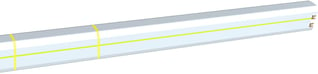
1 - Standard straight element (Standard)
Straight element with built-in conductors and pre-mounted connections, usable up to 55°C ambient temperature
Advantages:
Easy and fast connection, safe assembling
IP 23: Index of protection against access to dangerous parts and rain
Description
Feeds the mobile trolley and ensures the insulation and protection against accidental contact.
Product number and compatibilities
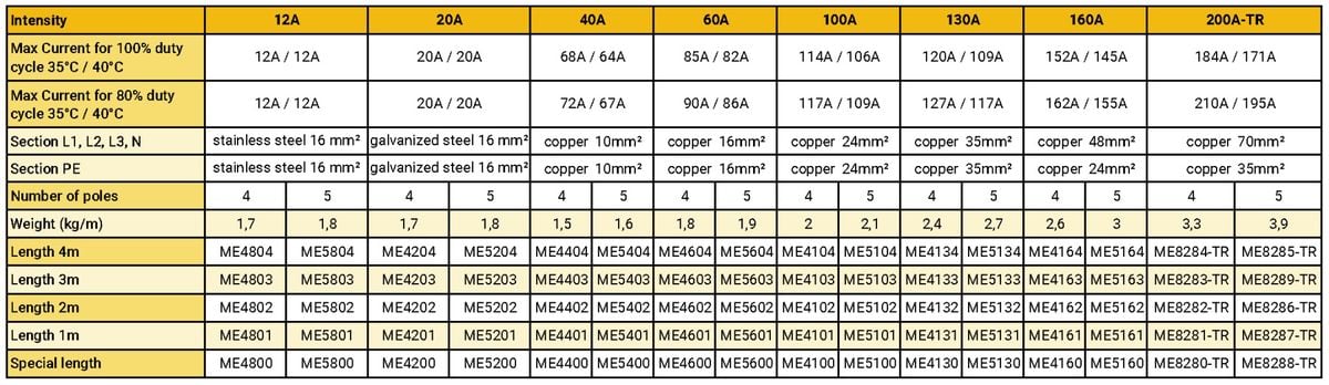
The standard straight elements are available with varying lengths of 4m, 3m, 2m, 1m, and special lengths, with or without lips, for high temperature up to +75°C (see ‘High temperature (H.T.) straight elements’), without earth marking (see ‘Straight elements without earth marking’). For curved elements, see ‘Curves’. The intensities indicated are valid for 50Hz, 60Hz and D.C. For 200A version with earth section identical to the phase section, refer to the section of obsolete products.
Available with protection lips?
Yes
Available in high temperature variant?
Yes
Available without P.E. ?
Yes
Available in curve version?
Yes
Technical data
Element with connection system fitted with built-in self-breaking screws, guaranteeing tightening at optimum torque. ‘Floating’ conductors fitted to manage the differences in expansion with the PVC line. The protection conductor is identified by a green-yellow band over the entire length of the element.
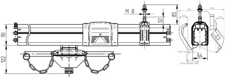
Overall dimensions
L (mm) : 64
H (mm) : 90
Weight (kg)
According to reference
Current rating
12A, 20A, 40A, 60A, 100A, 130A, 160A, 200A
Rated Voltage
750V
Rated Température
-30°C to +55°C
Material
Self-extinguishing PVC light grey
Mounting
Installation rules
Elements to be clipped in sliding hangers, end to end connection of elements by tightening the connections. For lengths above 140 meters, or when curves, transfer elements, or rigid power cables are fitted, please refer to the section ‘Expansion joints’ to determine if an expansion joint is required.Position the elements at a distance from support large enough to provide access to the connections and to position the accessories (covering flange, feed box): minimum recommended clearance of 65mm.
Mounting rules
1. Insert the lines in the sliding hangers
2. Connect the lines
Maintenance
See the rules of maintenance of the lines
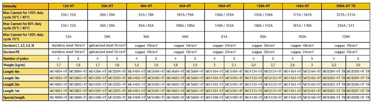
2 - High temperature straight element (High Temperature)
Straight element with built-in conductors and pre-mounted connections, usable up to 75°C ambient temperature.
Advantages:
Can be used up to +75°CIP 23: Index of protection against access to dangerous parts and rain
Description
Feeds the mobile trolley and ensures the insulation and protection against accidental contact.
Product number and compatibilities
The high temperature straight elements are available with varying lengths of 4m, 3m, 2m, 1m, and special lengths. Not fitted with protection lips, no version without earth marking. For curved elements, see ‘Curves’. The intensities indicated are valid for 50Hz, 60Hz and D.C.
Available with protection lips?
No
Available in high temperature variant?
No
Available without P.E. ?
No
Available in curve version?
Yes
Technical data
Element with connection system fitted with built-in self-breaking screws, guaranteeing tightening at optimum torque. ‘Floating’ conductors fitted to manage the differences in expansion with the PVC line. The protection conductor is identified by a green-yellow band over the entire length of the element. Caution: H.T. line cannot be fitted with dust-protecting lips, since the lip seal material is not appropriate for temperatures above 55°C.
Overall dimensions
L (mm) : 64
H (mm) : 90
Weight (kg)
According to reference
Current rating
12A, 20A, 40A, 60A, 100A, 130A, 160A, 200A
Rated Voltage
440VAC
Rated Temperature
-30°C to +75°C
Material
Self-extinguishing PVC white
Mounting
Installation rules
Elements to be clipped in sliding hangers, end to end connection of elements by tightening the connections. For lengths above 140 meters, or when curves, transfer elements, or rigid power cables are fitted, please refer to the section ‘Expansion joints’ to determine if an expansion joint is required. Position the elements at a distance from the support large enough to provide access to the connections and to position the accessories (covering flange, feed box): minimum recommended clearance of 65mm.
Mounting rules
1. Insert the lines in the sliding hangers, 2. Connect the lines
Mounting required tools
Maintenance
See the rules of maintenance of the lines
3 - Straight element without earth marking (Without PE)
Straight element without earth marking, with built-in conductors and pre-mounted connections, usable up to 55°C
Advantages:
All conductors may be used as active conductorsIP 23: Index of protection against access to dangerous parts and rain
Description
Feeds the mobile trolley and ensures the insulation and protection against accidental contact.

Product number and compatibilities
The straight elements with no marking of the protection conductor are available with varying lengths of 4m, 3m, 2m, 1m, and special lengths, with/and without protection lips. The references are identical to the standard line elements, but with ‘- B’ quoted after the reference, for example ME4404-B. Caution: the feedings and trolleys are specific: refer to the related sections. For ordering a version with lips, use a new reference replacing – B by – LVB: for example ME4404-B becomes ME4404-LVB in version with lips, and without earth marking. The intensities indicated are valid for 50Hz, 60Hz and D.C.
Available with protection lips?
Yes
Available in high temperature variant?
No
Available in curve version?
Yes
Technical data
PVC Line with connection system fitted with self-breaking screws, guaranteeing a tightening of the connections to the ideal torque. All conductors of the elements without earth marking can be active conductors and supply power or signal when a protection conductor is not required. The element is identified by a black band over the entire length
Overall dimensions
L (mm) : 64
H (mm) : 90
Weight (kg)
According to reference
Current rating
12A, 20A, 40A, 60A, 100A, 130A, 160A, 200A
Rated Voltage
750V
Rated Temperature
-30°C to +55°C
Material
Self-extinguishing PVC light grey
Mounting
Installation rules
Elements to be clipped in sliding hangers, end to end connection of elements by tightening the connections. For lengths above 140 meters, or when curves, transfer elements, or rigid power cables are fitted, please refer to the section ‘Expansion joints’ to determine if an expansion joint is required. Position the elements at a distance from the support large enough to provide access to the connections and to position the accessories (covering flange, feed box): minimum recommended clearance of 65mm. It is the responsibility of the fitter to precisely identify the D.C. current poles according to the requirements for the circuit.
Mounting rules
1. Insert the lines in the sliding hangers, 2. Connect the lines

Mounting required tools
Maintenance
See the rules of maintenance of the lines
4 - Straight element with rubber gasket (With lips)
Straight element with built-in conductors and pre-mounted connections, dust protectiongasket pre-mounted in factory, usable up to 55°C ambient temperature
Advantages:
Protection from dustIP 23: Index of protection against the access to the dangerous parts and the rain
Description
Feeds the mobile trolley and ensures the insulation and protection against accidental contact and dust.
Product number and compatibilities
The straight elements with gaskets are available in versions with lengths of 4m, 3m, 2m, 1m and special lengths, without earth marking (see ‘Straight elements without earth marking’), for maximum ambient temperature of 55°C. For curved element, see ‘Curves’. The intensities indicated are valid for 50Hz, 60Hz and D.C.
Available in high temperature variant?
No
Available without P.E. ?
Yes
Available in curve version?
Yes
Technical data
PVC line with connection system fitted with built-in self-breaking screws, guaranteeing tightening at optimum torque. Self-extinguishing elastomer gaskets. Designed to limit ingress of dust in the line. Index of protection: IP23. The sections with gaskets must be fitted with covering flanges or feed boxes appropriate to the gaskets. Caution: Use only simple single trolleys and carriers. The dust-protecting gaskets are not appropriate for temperatures above 55°C. The protection conductor is identified by a green-yellow band over the entire length of the element. Special elements are also available with dust-protecting devices.
Overall dimensions
L (mm) : 64
H (mm) : 102
Weight (kg)
According to reference
Current rating
12A, 20A, 40A, 60A, 100A, 130A, 160A, 200A
Rated Voltage
750V
Rated Température
-20°C to +55°C
Material
Self-extinguishing PVC light grey, black gaskets
Mounting
Installation rules
Elements to be clipped in sliding hangers, end to end connection of elements by tightening the connections. For lengths above 140 meters, or when curves, transfer elements, or rigid power cables are fitted, please refer to the section ‘Expansion joints’ to determine if an expansion joint is required. Position the elements at a distance from the support large enough to provide access to the connections and to position the accessories (covering flange, feed box): minimum recommended clearance of 65mm.
Mounting rules
1. Insert the lines in the sliding hangers, 2. Connect the lines
Mounting required tools
Maintenance
Repeat the application of silicone grease between the gaskets if excessive adhesion is observed. The assembling of the gaskets can be made in the workshop using specific tools, please enquire.
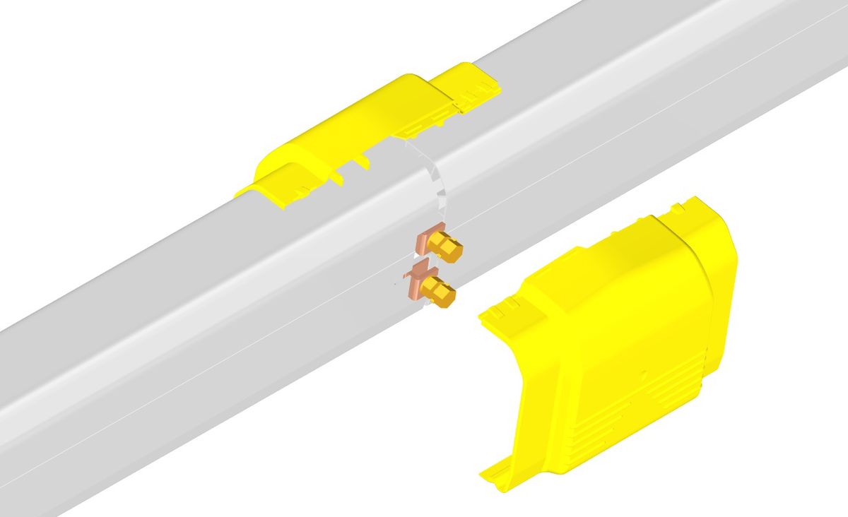
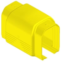
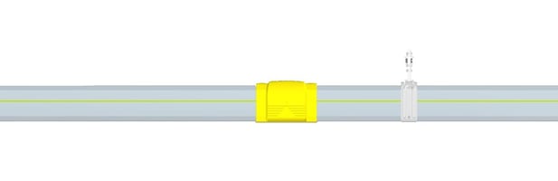
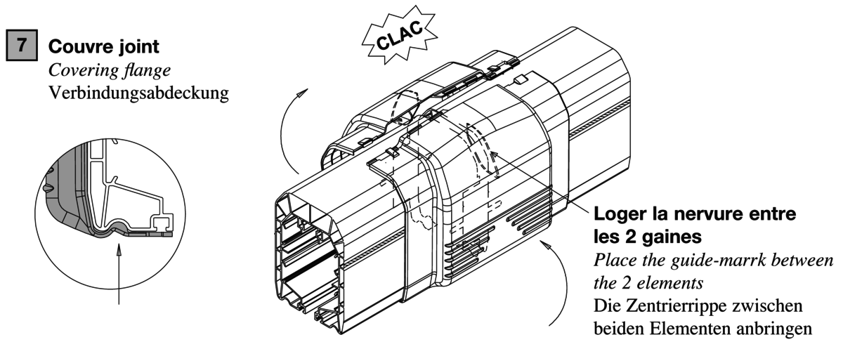
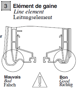
5 - Covering flange (Standard)
Accessory for electrical insulation of the junctions
Advantages:
Non-forgettable connection systemClipped-on assembling, no tools required
Description
The covering flange is used to protect the operator against direct contact with the connections. It also ensures the protection of the junctions against hard conditions of the environment. Assembling only possible if the heads of the connection screws have been correctly broken.
Product number and compatibilities
Ref. ME2000, This reference is for the junctions between standard straight elements, and for high temperature. Alternative versions: ME2000-CO for curves, ME2000-LV for lines with lips and MO2000-COLV for curves with lips
Available with protection lips?
yes, ME2000-LV
Available in curve version?
ME2000-CO
Technical data
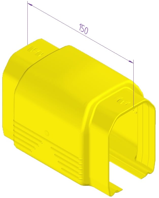
Overall dimensions
L (mm) : 94
H (mm) : 104
Z (mm) : 150
Weight (kg)
0,1 kg
Current rating
12A, 20A, 40A, 60A, 100A, 130A, 160A, 200A
Rated Voltage
750V
Rated Temperature
-30°C to +75°C
Material
Self-extinguishing thermoplastic
Mounting
Installation rules
Provide one element at each junction, outside feeding points. Choose the version for curves (ME2000-CO or ME2000-COLV), between curves but also between curve and straight element.
Mounting rules
1. Connect the two lines 2. Close the covering flange on the connection
Mounting required tools

Dismounting required tools

Maintenance
This element does not require any special maintenance.
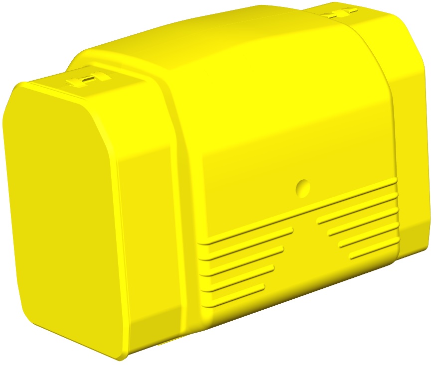
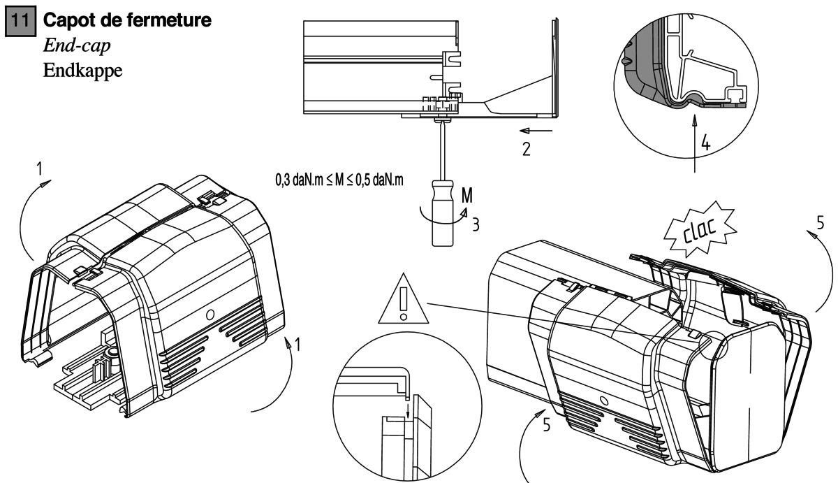
6 - End-cap (Standard)
Provides the insulation of live elements at the ends of the line
Advantages:
Clip-on assembling, no tools neededIP23 Protection
Description
The end-cap must be placed at each end of the line to ensure operator protection. Its use is required for CE conformance.
Product number and compatibilities
ME2400
Available with protection lips?
compatible
Available in high temperature variant?
compatible
Available without P.E. ?
compatible
Available in curve version?
compatible
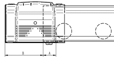
Technical data
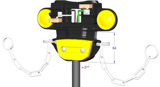
Area with no access to the trolley A: 35mm. Extra Length at end of line B: 96mm
Overall dimensions
L (mm) : 94
H (mm) : 109
Z (mm) : 152
Weight (kg)
0,2 kg
Current rating
12A, 20A, 40A, 60A, 100A, 130A, 160A, 200A
Rated Voltage
750V
Rated Temperature
-30°C to +75°C
Material
Self-extinguishing thermoplastic
Mounting
Installation rules
To be positioned end of line. Provide enough space so as not to impede line expansion (minimum of 6cm for 50metres, minimum of 2.5cm for 100metres)
Mounting rules
Before hand, remove the connection screws fitted to the rail, 1. Open the end-cap, 2 Insert the part with straight angles, 3. Tighten the screw, 4. Close the cap on the line making sure to place the grooves on one another.
Mounting required tools

Dismounting required tools
Maintenance
This element does not require any special maintenance.
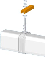
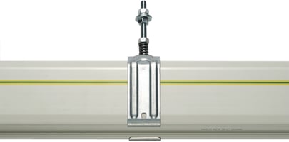
7 - Sliding hanger (Standard)
Supports the line and allows expansion, self-aligning with the line on assembly.
Advantages:
Self-alignment systemEasy assembling by screw and simple clip-on of the line
Description
The sliding hanger is used to support the line and allow its expansion. The line is inserted by simple insertion upwards. The suspension is fixed to the bracket by nuts to provide precision adjustment of alignment in height.
Product number and compatibilities
ME1510: sliding hanger fully pre-mounted, fits brackets and line elements of Mobilis Elite line. For suspension with anchoring, refer to ‘Fixed hangers’.
Technical data
With screw M8
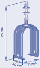
Overall dimensions
L (mm) : 71
H (mm) : 176
Z (mm) : 40
Weight (kg)
0,1 kg
Rated Temperature
-30°C to +75°C
Material
zinc coated steel
Mounting
Installation rules
Number of sliding hangers per installation: Per straight element: For external installations of 130/160/200A with lengths above 150m, the outside section requires 3 sliding hangers per element of 4m. For high temperature elements of 130/160/200A under temperatures above 60°C and above 70°C for the other high temperature line intensities, provide 3 sliding hangers per element of 4m. For any other straight element, provide 2 sliding hangers per straight element plus a sliding hanger of 350mm at end of the line. Per pre-mounted feed: provide 3 sliding hangers per feed of 4m and 2 sliding hangers per feed of 1m. Per introduction gate: Do not provide sliding hangers as these are included in the reference of the introduction gate. Per ventilation element: provide the same number of sliding hangers as for the straight element. Per curved element: If the angle of the curve is below 90°C and the expanded length equal to or above 2m, provide 2 sliding hangers per curve. In the other cases, provide 3 sliding hangers per curve. Per transfer element: Do not provide a sliding hanger but fixed hangers. Per circuit interruption element: For external installations of 130/160/200A and lengths above 150m, the outside section requires 3 sliding hangers per element of length above 3m. For any other circuit interruption element, provide 2 sliding hangers per straight element. Per expansion joint: provide 2 sliding hangers per expansion joint.
Mounting rules
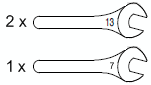
Simply clip-on the line between the sides of the sliding hanger. Requires two wrenches No. 13 for assembling on the support. Position the sliding hanger 350mm from the end, then every 2m for 2 sliding hangers per line and every 1.33m for 3 sliding hangers per line.
Mounting required tools

Dismounting required tools
Maintenance
Preventive maintenance of external or dusty installations: check that the lines slide freely
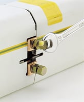
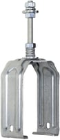
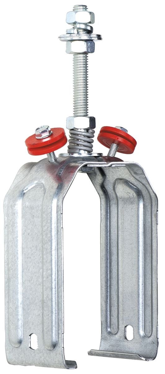
8 - Fixed hanger (Standard)
Fixes the position of the line and special curved elements and transfer elements
Advantages:
Fitted with red discs of visual locationSelf-alignment system
Description
The fixed hanger is built on the basis of the sliding hanger. It is entirely pre-mounted and equipped with 2 compression screws immobilising the profile of the line elements.
Product number and compatibilities
ME1500
Technical data
M8 screw, delivered with 2 built-in anchoring screws and red locating discs
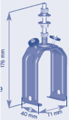
Overall dimensions
L (mm) : 71
H (mm) : 176
Z (mm) : 40
Weight (kg)
0,1 kg
Rated Temperature
-30°C to +75°C
Material
Zinc coated steel
Mounting
Installation rules
The fixed hangers are always placed on a same element of the line. 2 items on the straight elements or the transfer elements, 2 or 3 items on the curves according to the expanded length. Place the fixed hangers midway in the line between 2 expansion joints (lines with transfer elements and/or curves: see special rules in these sections)
Mounting rules
Clip-on the elements of the line, place them longitudinally: tighten fully the 2 compression screws.
Mounting required tools
Dismounting required tools
Maintenance
This element does not require any special maintenance.
9 - Bracket (Standard)
Ensures the mechanical link connection between the structure of the frame and the sliding hangers, fixes the position of the line in relation with the running rail.
Advantages:
Available in fast assembling versionVarious lengths available
Description
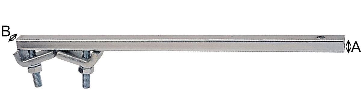
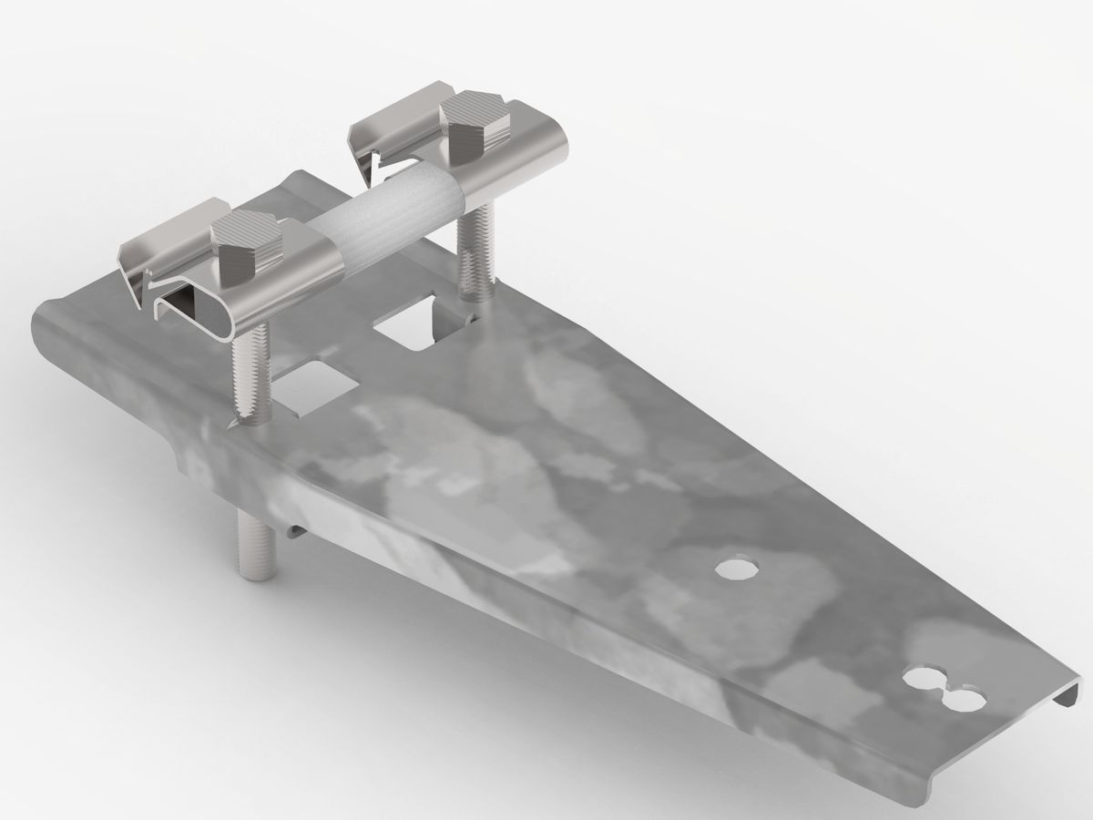
The fixing bracket allows to maintain the clearance between the line and the travel path. This clearance must be as parallel as possible. The Bracket must be chosen according to the wing-thickness of the beam on which it is attached, according to the centre distance between the beam and Mobilis and according to the weight to support. The standard bracket requires access from both sides of the beam for tightening the tightening plates. The position of the hole must be adjusted in relation to the running rail. 2 section profiles are available and will be selected based on the load to be supported (weight of element, number of suspensions by element, trolley, parasitic load – ice). The fast assembling clamped bracket requires access from only one side, in abutment to the screws. The hole is automatically positioned in relation to the beam edge. Restrictions of use of the fast assembling bracket: – only for interior service – not for line with expansion joint – not for line with dust protection lips – not for lines with transfer elements
Product number and compatibilities
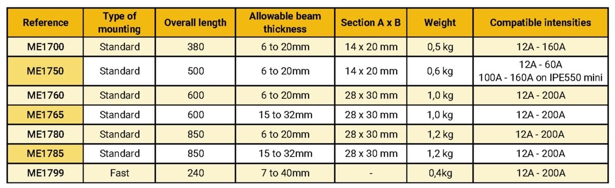
The following references include several types of supports: fast assembling or not, and for beams up to 20mm or 32mm of thickness.
Technical data
Brackets in 1000mm length are Available on request. The bending resistance of these brackets have to be considered on a case-by-case basis according to the cantilever distance and the overhung load.
Mounting
Installation rules
Number and position according to the rules for placing the sliding hangers.
Mounting rules
Align the assembling holes of the sliding hangers in parallel to the travel path
Mounting required tools
Dismounting required tools
Maintenance
This element does not require any special maintenance.
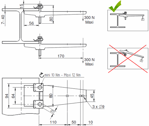
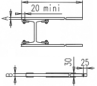
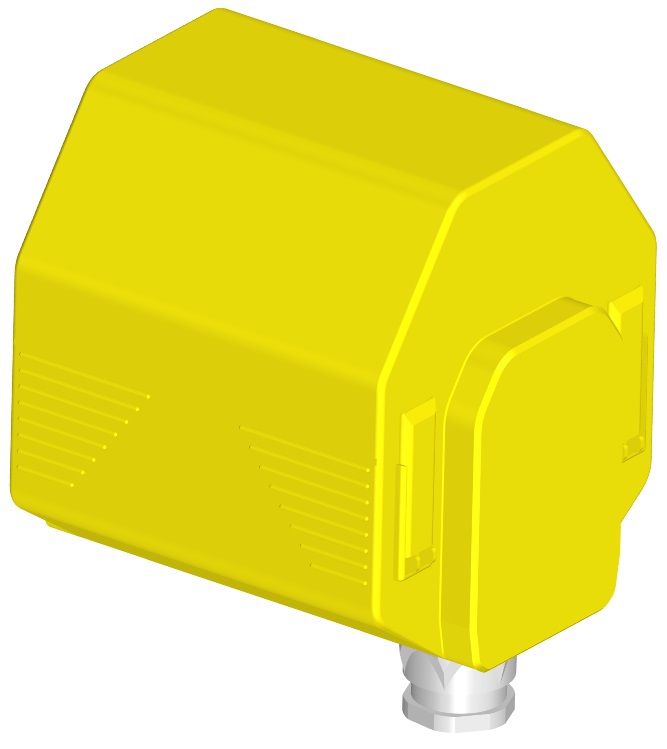
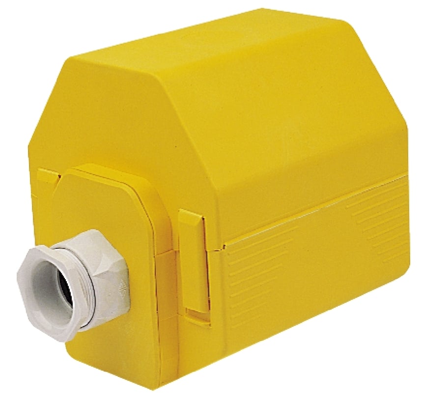
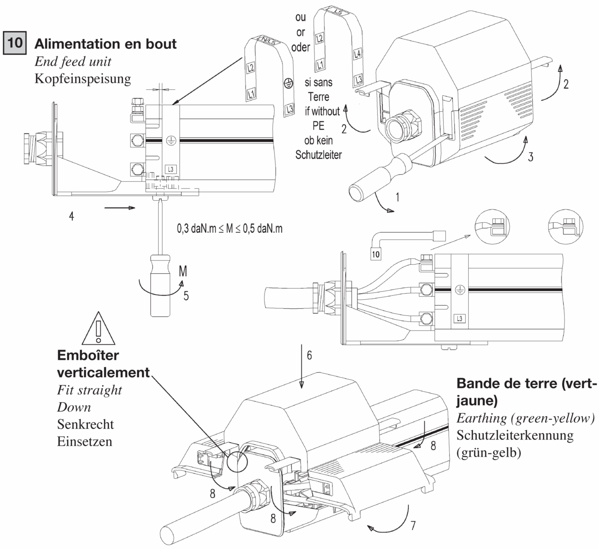
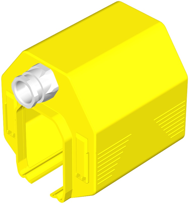
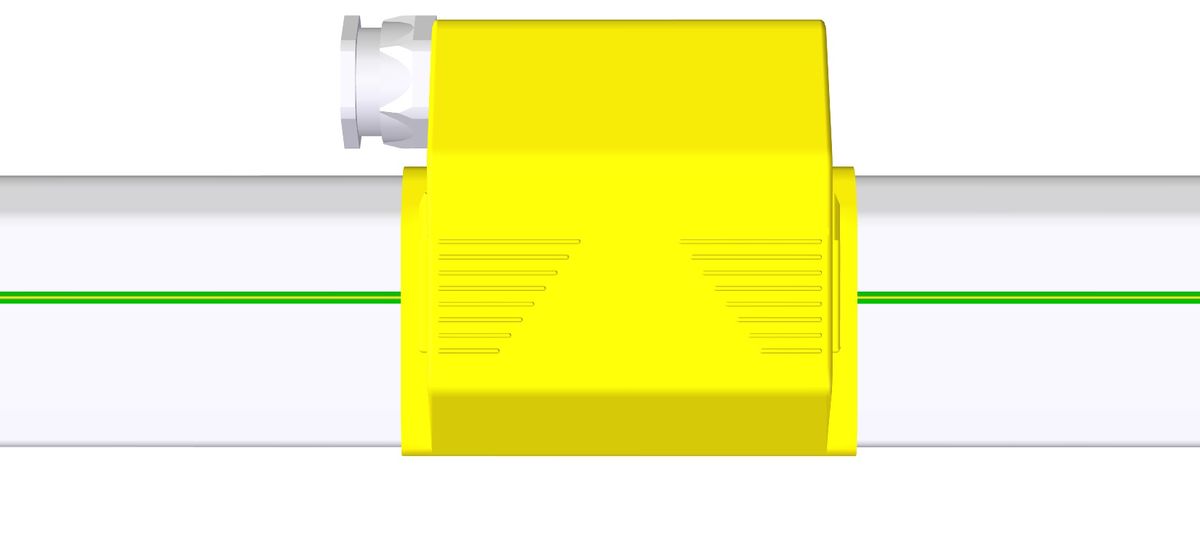
10 - End Line Feed Box (Standard)
Interface accessory for the electrical connection of the line at end of line
Advantages:
Horizontal cable outlet (outlet through bottom possible), M25, M32, M40 cable glandsIP 23: Index of protection against access to dangerous parts and rain
Description
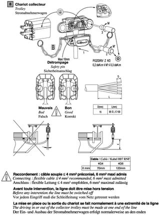
For electrical connection of the installation end of line. Feeds in line are also available. For copper and aluminum flexible cable. For use with aluminum cables, provide bi-metallic cable eye stiffeners and cables of minimum section of 16mm² in conformance with Standard NF EN 60204-32 §13.2
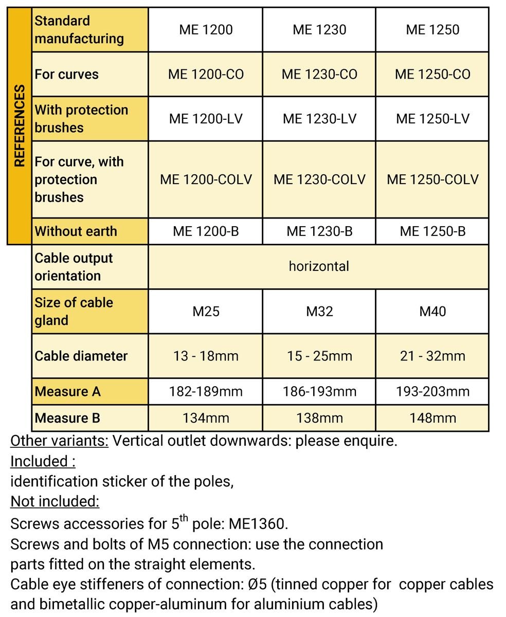
Product number and compatibilities
ME1200: Horizontal outlet with M25 cable gland for cables Ø13 mm to Ø19 mm. ME1230: Horizontal outlet with M32 cable gland for cables Ø15 mm to Ø25 mm. ME1250: Horizontal outlet with M40 cable gland for cables Ø21 mm to Ø32 mm. Option: vertical outlet downwards: please enquire. Supplied with identification sticker of the poles. Screws and bolts of M5 connection not included, use the connection parts fitted on the straight elements. Cable eye stiffeners of connection not included, galvanized copper for cable coppers and bimetallic copper-aluminum cable eye stiffener not included for aluminium cables: cable eye stiffeners Ø5.
Available with protection lips?
Compatible
Available in high temperature variant?
Compatible
Available without P.E. ?
Yes
Available in curve version?
Compatible
Technical data
Area on line with no access to the trolley: 35mm. Extra Length in end of line: 148mm, Tightening capacity of the cable glands: M25 for cables Ø13 to 18 mm, M32 for cables Ø18 to 25 mm and M40 for cables Ø22 to 32mm
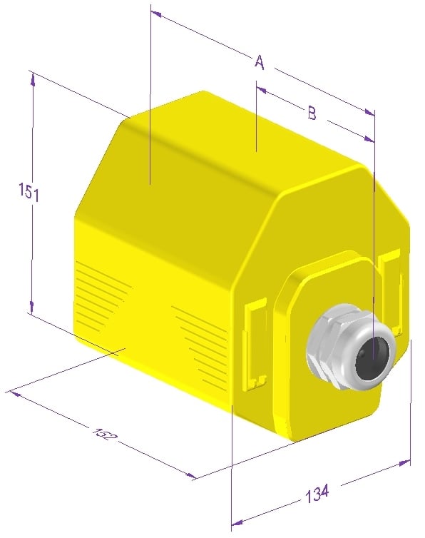
Overall dimensions
L (mm) : 134
H (mm) : 151
Z (mm) : 203
Weight (kg)
0,4 kg
Current rating
12A, 20A, 40A, 60A, 100A
Rated Voltage
750V
Rated Temperature
-30°C to +75°C
Material
Self-extinguishing thermoplastic
Mounting
Installation rules
For choosing an end- line feeding point, consider the overall length of the line for calculating the voltage drop. Provide a flexible wiring so as not to impede the expansion of the line. Fitted in place of an end-cap.
Mounting rules
The cable should not impede the free expansion of the line: provide adequate free loop of flexible cable. Provide cable eye stiffeners of connection Ø5mm, screws and bolts not included.
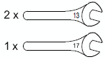
Mounting required tools
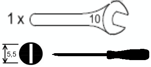
Dismounting required tools
Maintenance
See the rules of maintenance of the lines
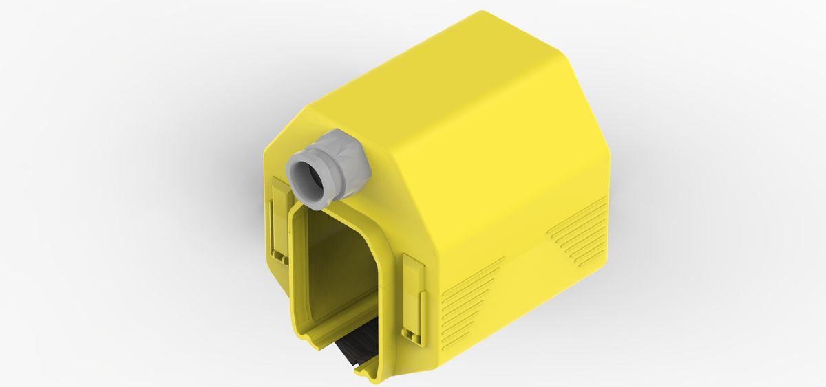
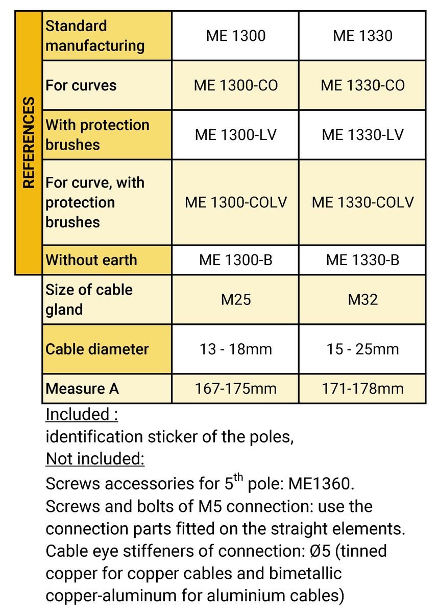
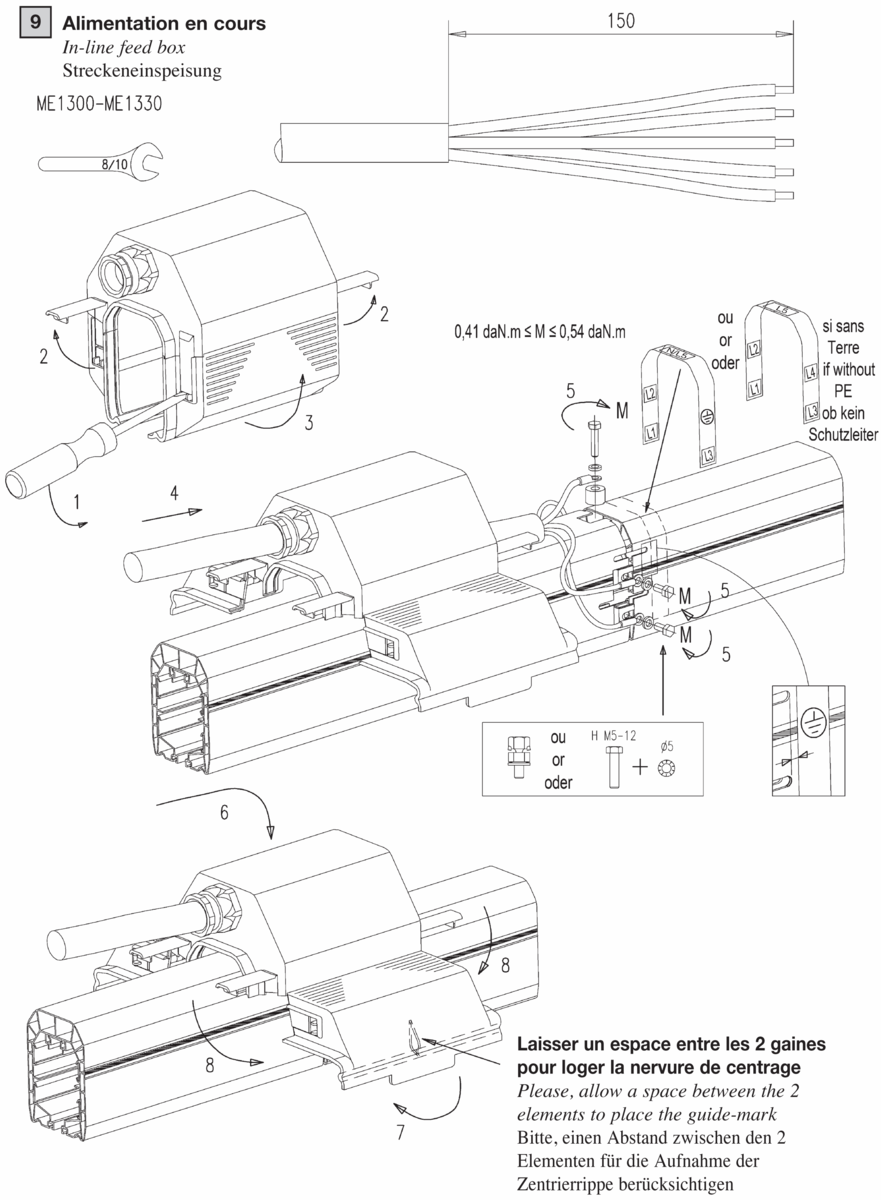
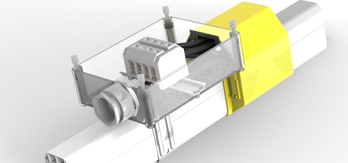
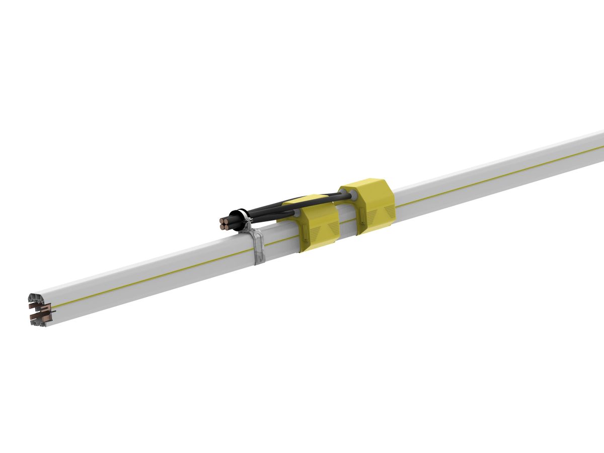
11 - M25-M32 in-line feed box (Standard)
Interface accessory for the electrical connection of the line on a connection in-line
Advantages:
In-line feed reduces the voltage dropsIP 23: Index of protection against access to dangerous parts and rain
Description
To be inserted in replacement of a covering flange for the electrical connection of the installation in-line. End feeds are also available. For cable of flexible copper and flexible aluminum. For use with aluminum cables, provide bi-metallic cable eye stiffeners and cables of minimum section 16mm² in accordance with Standard NF EN 60204-32 §13.2
Product number and compatibilities
ME1300: with M25 cable gland for cables Ø13 mm to Ø19 mm, ME1330: with M32 cable gland for cables Ø15 mm to Ø25 mm. Option: version with lips ME1300-LV and ME1330-LV, version for curve ME1300-CO and ME1330-CO. Supplied with identification sticker of the poles. Screws and bolts of M5 connection not included, use the connection parts fitted on the straight elements. Cable eye stiffeners of connection not included: Ø5. Set of spacer and screws and bolts for connection of 5th pole: Ref. ME1360
Available with protection lips?
Yes
Available in high temperature variant?
Compatible
Available without P.E. ?
Yes
Available in curve version?
Compatible
Technical data
Feeding with direct connection by eye terminal Ø5mm (no connection plate), screws and bolts not included. Appropriate for the standard and high temperature ranges. Tightening capacity of the cable glands: M25 for cables Ø13 to 18 mm and M32 for cables Ø18 to 25 mm
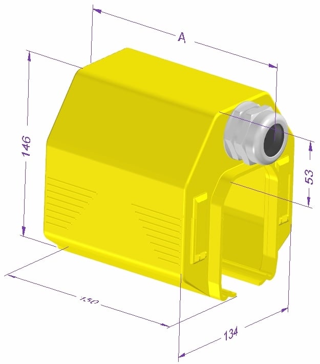
Overall dimensions
L (mm) : 134
H (mm) : 146
Z (mm) : 178
Weight (kg)
0,3 kg
Current rating
12A, 20A, 40A, 60A, 100A
Rated Voltage
750V
Rated Temperature
-30°C to +75°C
Material
Self-extinguishing thermoplastic
Mounting
Installation rules
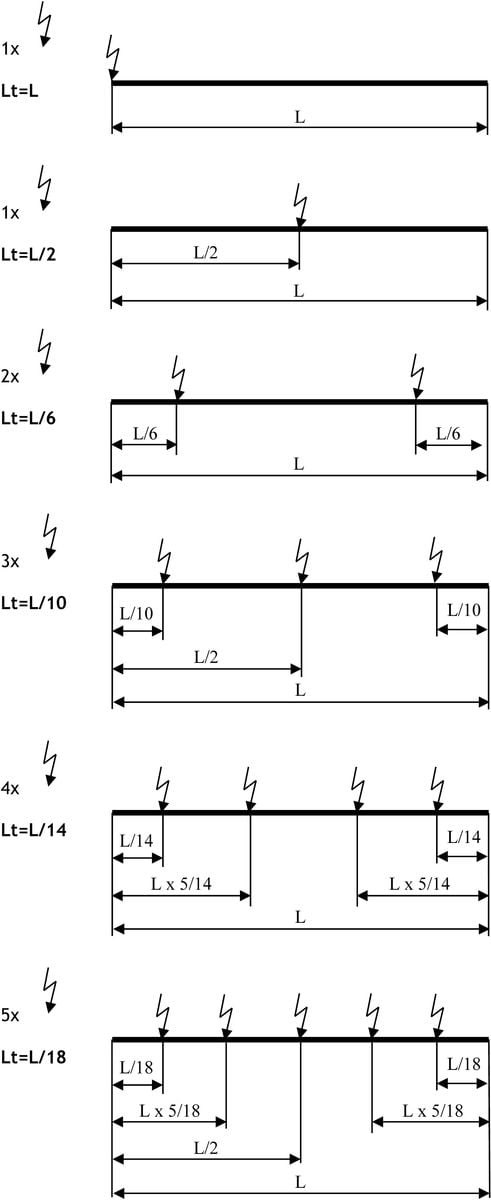
Providing one or more feeding point in line rather than end-of-line reduces the voltage drop (?U=Lt.?3.Z.I) and allows to choose a lower intensity because the length ‘Lt’ taken into account in the calculation varies according to the number of feed boxes. Providing a feeding point midway in the line reduces by half the voltage drop, as the ‘Lt’ section taken into account equals half the length of the line. For more than one feeding point in line, please review the following graph for the position of the points and related voltage drops.
Mounting rules
The cable should not impede the free expansion of the line: provide adequate free loop of flexible cable. Provide cable eye stiffeners of connection Ø5mm, screws and bolts not included.
Mounting required tools
Dismounting required tools
Maintenance
See the rules of maintenance of the lines
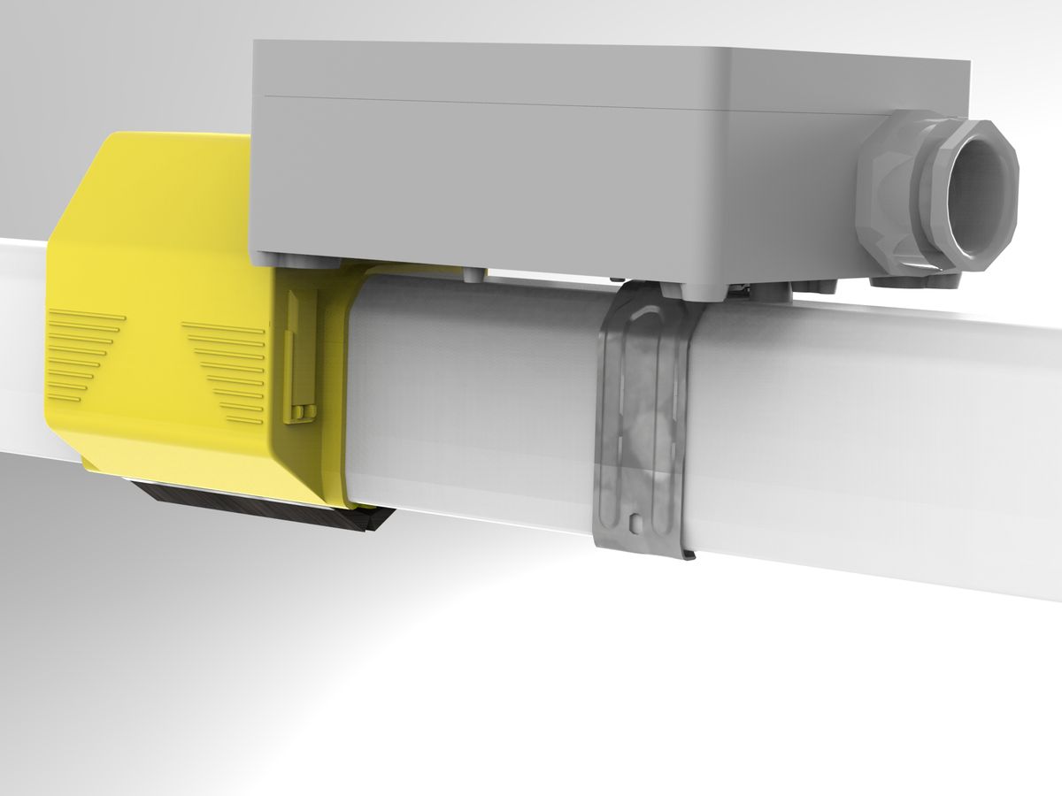
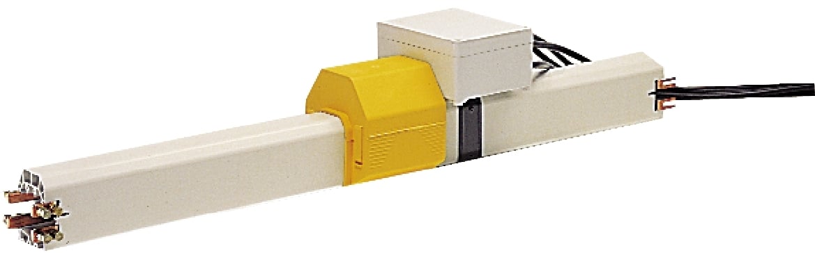
12 - M40 in-line feed (Standard)
Interface accessory for the electrical connection of the line at a junction in-line
Advantages:
In-line feed reduces the voltage dropsIP 23: Index of protection against access to dangerous parts and rain
Description
To be inserted in replacement of a covering flange for the electrical connection of the installation in-line. End feeds are also available. For cable of flexible copper and rigid aluminum. When aluminum cables are used, please request the specific instructions for rigid cables and provide cables of minimum section 16mm² in accordance with Standard NF EN 60204-32 S13.2
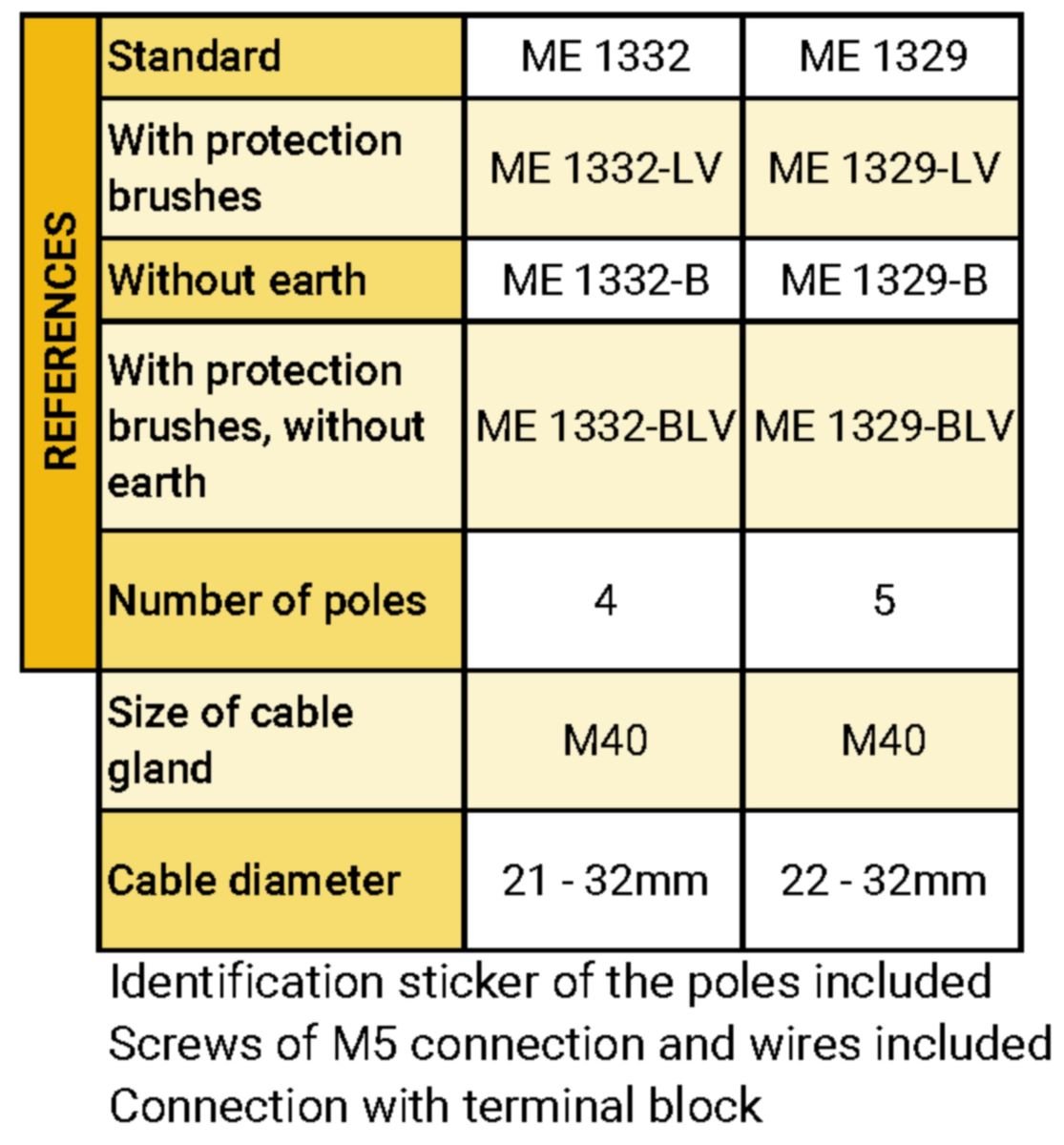
Product number and compatibilities
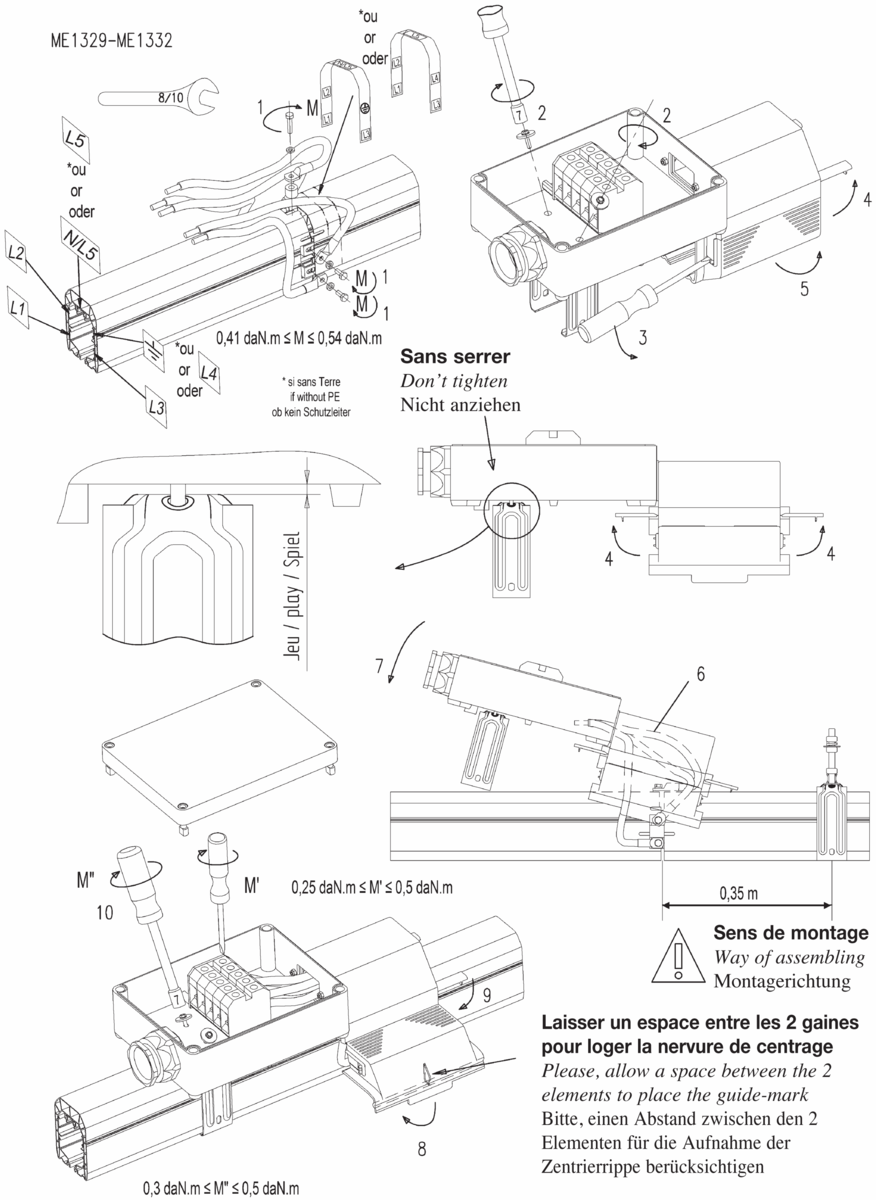
ME1332: Version 4Poles with M40 cable gland for cables Ø21 mm to Ø32 mm, ME1329: Version 5poles with M40 cable gland for cables Ø21 mm to Ø32 mm. Versions with lips ME1332-LV and ME1329-LV. Supplied with sticker of identification of the poles. Screws and bolts of M5 connection and connection wire included. For version without earth marking, add – B after the reference.
Available with protection lips?
Yes
Available in high temperature variant?
Compatible
Available without P.E. ?
Yes
Available in curve version?
No
Technical data
Capacity of the terminal block: 35mm², Tightening capacity of the cable gland: for cables Ø22 to 32mm
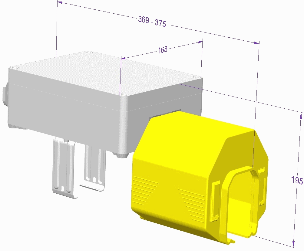
Overall dimensions
L (mm) : 164
H (mm) : 195
Z (mm) : 375
Weight (kg)
1,7 kg
Current rating
12A, 20A, 40A, 60A, 100A
Rated Voltage
750V
Rated Temperature
-30°C to +75°C
Material
Self-extinguishing thermoplastics, zinc coated steel
Mounting
Installation rules
Providing one or more feeding point in line rather than end-of-line reduces the voltage drop (?U= Lt.?3.Z.I) and allows to choose a lower intensity because the length ‘Lt’ taken into account in the calculation varies according to the number of feed boxes. Providing a feeding point midway in the line reduces by half the voltage drop, as the ‘Lt’ length taken into account equals half the length of the line. For more than one feeding point in line, please review the following graph for the position of the points and related voltage drops. With the version for curves, no limit for the radius at the curve-straight element junction, otherwise minimum radius R… at the curve-curve junction.
Mounting rules
The cable should not impede the free expansion of the line: provide adequate free loop of flexible cable. If single wire aluminium cables are used (multistrand prohibited), use contact lubricant.
Mounting required tools
Dismounting required tools
Maintenance
See the rules of maintenance of the lines
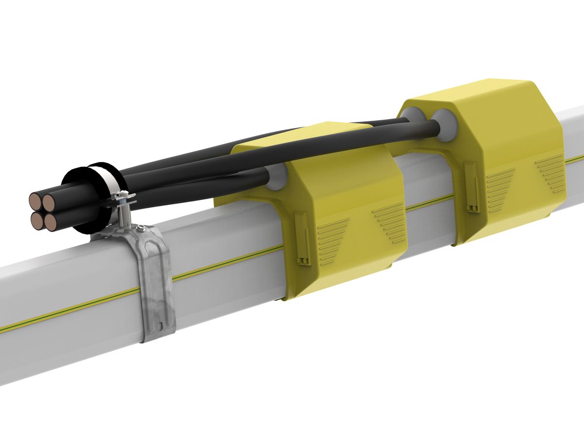
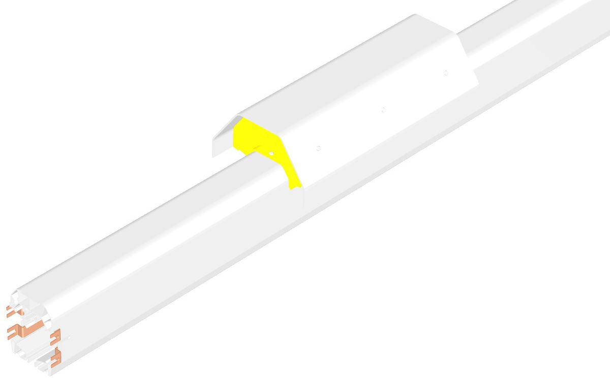
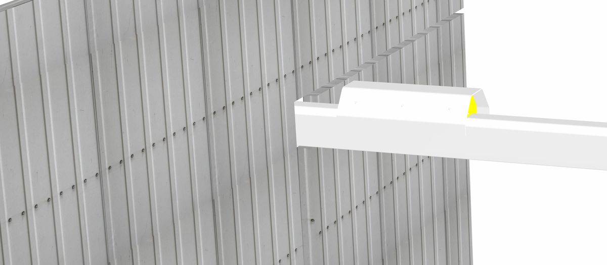
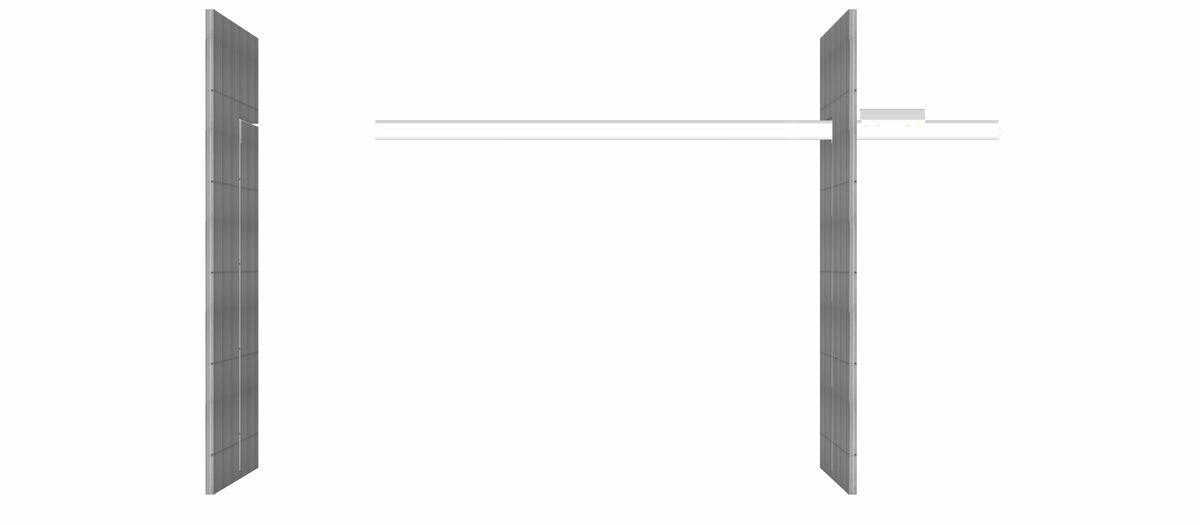
13 - Pre -mounted feed box on straight element (Standard)
Interface accessory for the electrical connection of the pre-mounted line on a straight element
Advantages:
Prewired with flexible cableDelivered with cable of 2m length
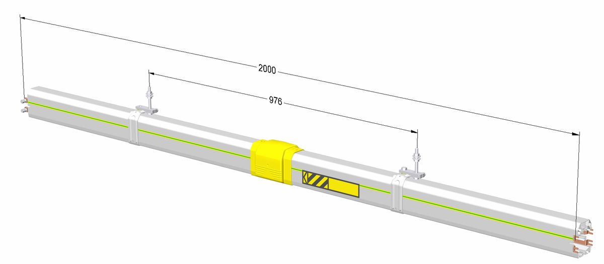
Description
Pre-mounted on 1 or 4m of standard line element, renovation with 2m cable for standard version. Connecting box aside required. L 4m: provide 3 sliding hangers, L 1m: provide 2 sliding hangers.
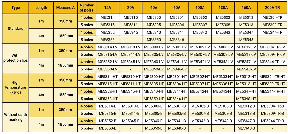
Product number and compatibilities
The pre-mounted feed boxes are offered in standard versions of 1m or 4m using the references of the following table, for versions withsatnding high temperature up to +75°C, add – HT after the reference, or for versions with dust protection lips, add – LV after the reference. Version without earth marking: add – B after the reference.
Available with protection lips?
Yes
Available in high temperature variant?
Yes
Available without P.E. ?
Yes
Available in curve version?
No
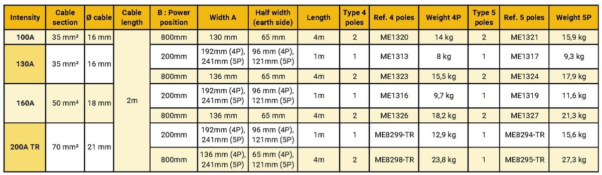
Technical data
Feeding width and weight are shown as dimension A and by the indications of the table of references.
Weight (kg)
see table
Current rating
100A, 130A, 160A, 200A-TR
Rated Voltage
750V
Rated Température
-30°C to +55°C
Material
Self-extinguishing thermoplastic, zinc coated steel
Mounting
Installation rules
Fitted in place of a straight element. Provide a connecting box aside (not supplied). L = 4m: 3 sliding hangers. L = 1m: 2 sliding hangers. Providing one or more feeding point in line rather than end-of-line reduces the voltage drop (?U = Lt.?3.Z.I) and allows to choose a lower intensity because the length ‘Lt’ taken into account in the calculation varies according to the number of feed boxes. Providing a feeding point midway in the line reduces by half the voltage drop, as the ‘Lt’ section taken into account is half the length of the line. For more than one feeding point in line, please review the following graph for the position of the points and related voltage drops.
Mounting rules
1. Clip-on the line in the sliding hangers, 2. Connect the line element at the ends, 3. Connect the cables in the box aside. The cable should not impede the free expansion of the line. Provide adequate free loop before the junction box.
Mounting required tools
Dismounting required tools
Maintenance
See the rules of maintenance of the lines
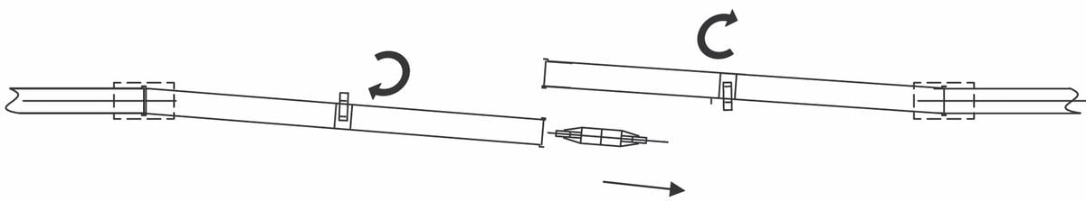
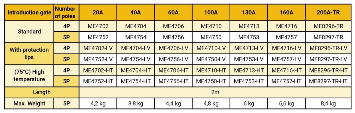
14 - Introduction gate (Standard)
Allows trolleys to be removed or inserted in-line.
Advantages:
Easy extraction of the trolley from the lineSliding hangers included
Description
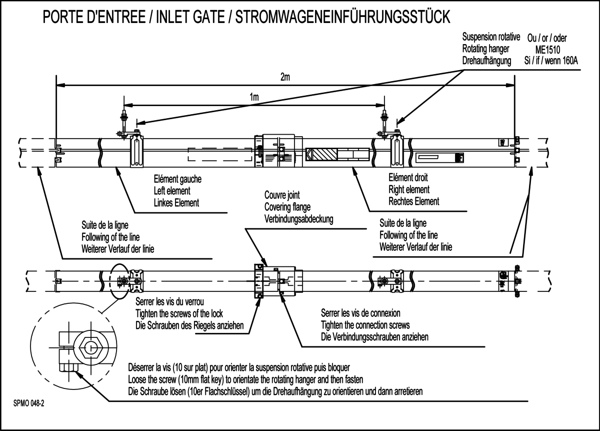
Introduction gates are designed to facilitate access to the collector trolleys, mainly for maintenance purposes. The introduction gate has a standard length of 2m and is supported by 2 special sliding hangers for the lateral displacement of the two line sections. It replaces a standard element of 2 meters. The connexion screw are reusable. Caution: the electrical supply to the line must be cut off before opening the introduction gate.
Product number and compatibilities
The references and their alternative versions are described in the following table
Available with protection lips?
Yes
Available in high temperature variant?
Yes
Available without P.E. ?
Yes, add -B behind the standard reference
Available in curve version?
No
Technical data
The introduction gate adds 0.6 kg to the weight of the standard equivalent element of 2m.
Weight (kg)
According to reference
Current rating
20A, 40A, 60A, 100A, 130A, 160A, 200A-TR
Rated Voltage
According to chosen range
Material
Self-extinguishing PVC light grey, self-extinguishing thermoplastic, zinc coated steel, copper
Mounting
Installation rules
To be located generally in a maintenance area
Mounting rules
1. Install the swivelling suspensions 2. Clip-on the straight elements of the introduction gate in the swivelling sliding hangers 3. Connect the straight elements to each other 4. Position the covering flange 5. Lock the swivelling sliding hanger
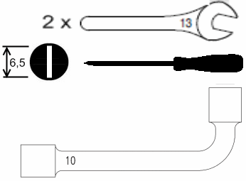
Mounting required tools
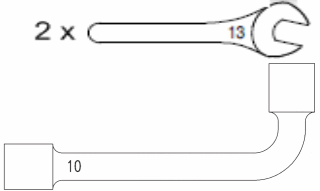
Dismounting required tools
Maintenance
See the rules of maintenance of the lines
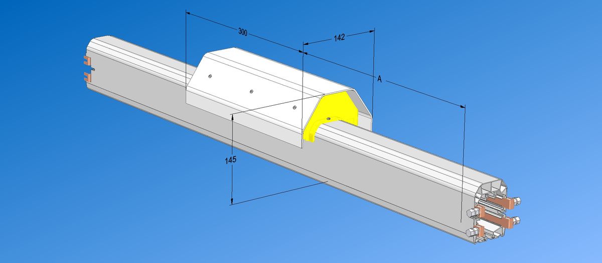
15 - Ventilation element (Standard)
Limits condensation in a line with a warm section (interior) and a cold section (exterior) of a building.
Advantages:
Limits condensationPre-mounted
Description
The purpose of the ventilation element is to limit condensation in a line with a warm section (inside the factory) and a cold section (outside the factory).
Product number and compatibilities
The ventilation element is available for standard version of 1m and 4m with the ventilation element fitted midway of the line, alternatives are available for High-Temperature (75°C) or with lips. See the references below.
Available with protection lips?
Yes
Available in high temperature variant?
Yes
Available without P.E. ?
Yes
Available in curve version?
No
Technical data
Add 0.5 kg to the weight of the standard equivalent element
Overall dimensions
L (mm) : 142
H (mm) : 145
Z (mm) : 300
Weight (kg)
According to reference
Current rating
12A, 20A, 40A, 60A, 100A, 130A, 160A, 200A-TR
Rated Voltage
According to reference
Material
PVC and self-extinguishing thermoplastic, copper
Mounting
Installation rules
The ventilation element is to be fitted like a standard element at the exit of the building (at the start of the cold area). The edge of the PVC cap must stand in the cold area at a distance of 200 to 500 mm from the hot area. Provide 2 sliding hangers, with a centre axis distance of 500mm for a 1m element, and of 2m for a 4m element.
Mounting rules
The edge of the PVC cap must be installed in the cold area at a distance of 200 – 500 mm from the hot area. The element is supported by 2 sliding hangers with a centre axis distance of 500 mm for 1m elements, 1000mm for 4m elements. 1. Insert the lines in the sliding hangers, 2. Connect the lines
Mounting required tools
.png?width=318&name=mont004_zoom%20(1).png)
Dismounting required tools
Maintenance
See the rules of maintenance of the lines
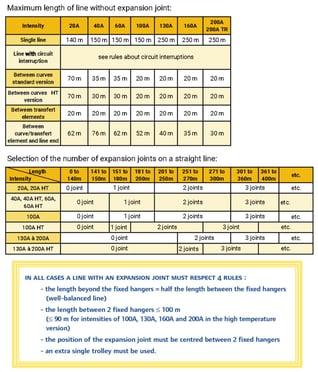
16 - Expansion Joint (Standard)
Absorbs the difference in expansion between the line and the carrying structure.
Advantages:
Can be managed like 2m elementUseless below 140m, even more for high intensities
Description
The expansion joint is a line accessory which is designed to absorb the difference in expansion between the support structure and the Mobilis Elite line within the whole temperature range of the product, thereby ensuring the continuity of the electrical supply for the conductors and also the mechanical continuity for the sliding of the brushes and the trolley guides. In all cases, an expansion joint requires the use of an extra single current collector to guarantee the current capacity and the quality of the electric contact at the cross-over point of the expansion joint. The length of the line section is, among other factors, dependent on the absorption capacity of the expansion joint. This is why line lengths without expansion joints cannot be reproduced between two fixed hangers on lines with expansion joints.

Product number and compatibilities
References of standard version in the following table, add – LV after the reference to order with lips and – HT to order version for high temperature (up to +75°C instead of +55°C).

Available with protection lips?
Yes
Available in high temperature variant?
Yes
Available in curve version?
No
Technical data
Overall dimensions
L (mm) : 146
H (mm) : 151
(mm) : 2000
Weight (kg)
According to reference
Current rating
20A, 40A, 60A, 100A, 130A, 160A, 200A
Material
Self-extinguishing PVC and thermoplastic
Mounting
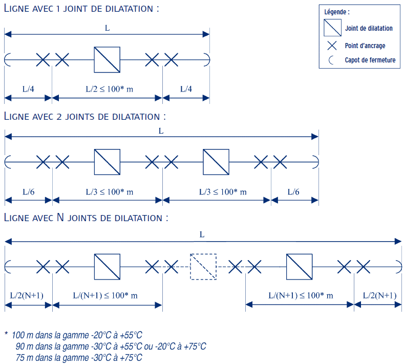
Installation rules
General case: Refer to the following diagram and the technical data for the layout of the expansion joints. Whenever the installation includes rigid cables impeding the expansion of the line, please request from us the Instruction Sheet SPST326.
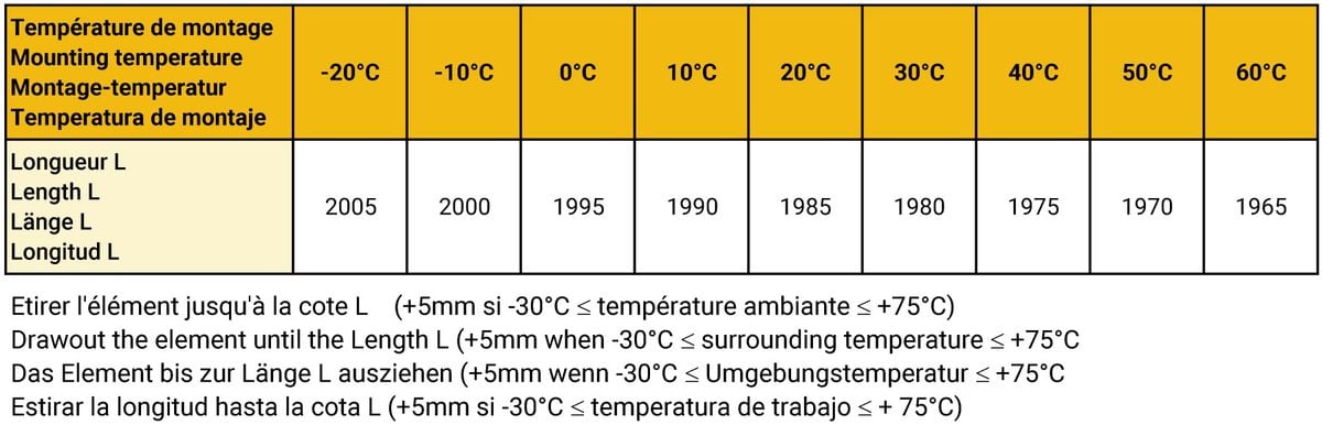
Mounting rules
The expansion joint must always be placed exactly at mid-point between two fixed hangers.
Increase the setting Length by +5mm if the surrounding working temperature is from -30°C to +75°C.
Maintenance
See the rules of maintenance of the lines.
17 - Horizontal curve (Curves)
Curved element bent in the horizontal plane with built-in conductors and pre-mounted connections.
Advantages:
Fits exactly the layout of the circuitAllows to build all radii
Description
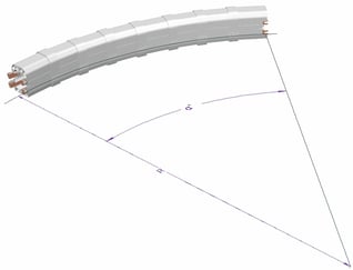
The curves are prepared in factory with the precise radius and angle of curve needed to maintain the feeding line at a constant distance from the travel path. Can be made for all intensities, standard range (maximum of 55°C) and high temperature (maximum of 75°C), with or without dust-protecting lips, with or without earth marking, for curve radii of 800mm (for lower radii, please enquire) up to infinity. They require the use of articulated trolleys. For intensities up to 130A, use curved covering flanges (ME2000-CO) or special feed boxes for curves (ME1300-CO, ME1330-CO, ME1332-CO or ME1329-CO) to be fitted to their junctions. Standard covering flanges and feed boxes for intensities 160A and 200A, the curves must be suspended by fixed hangers. Special curves can be made on request, including with straight sections at the ends, or vertical curves: please enquire.
Product number and compatibilities
The reference indicates the direction of the curved element required (earth inside or outside). The line should be set to make the earth side visible so as to facilitate access to the trolley connection plate. To order the version with lips, add ‘- LV’ after the reference, for high temperature versions, add ‘- HT’ after the reference, for versions without earth marking, add ‘- B’ after the reference. When ordering, provide additional data for radius R and angle a.

Available with protection lips?
Yes
Available in high temperature variant?
Yes
Available without P.E.?
Yes
Technical data
Please provide the following data: radius, angle, reference of the curve. Minimum radius: 800mm, for lower radii, please enquire. Maximum radius: no limit. Angle: up to 120° per element for intensity 20A to 100A, up to 90° for intensities 130A to 200A, above this, please enquire. The feeding line must maintain a constant distance from the travel path of the mobile device requiring current and must therefore follow a parallel path. The special curved elements (in the horizontal plane) are designed for this type of installation. Other features of the element: see section on straight elements. Maximum travel speed in the curves: 70m/min
Weight (kg)
kg / m identical to the standard, depending on the developed length
Current rating
20A, 40A, 60A, 100A, 130A, 160A, 200A
Rated Voltage
750V or 440V according to chosen range
Rated Temperature
-20°C to +55°C
Material
Gray PVC and self-extinguishing thermoplastic
Mounting
Installation rules
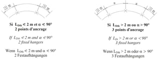
ASSEMBLING: When assembling, scrupulously follow the specifications in the assembly instructions for curved elements SPMO 064. The curve must not move in the sliding hangers and shall be regarded as a fixed point. Always use fixed hangers to support it, quantities to be defined according to the 2 following rules: RULE 1: If the expanded length of the curve is equal to or below 2m AND if the angle of the curve is equal to or below 90°, provide 2 fixed hangers per curve. RULE 2: If the expanded length of the curve is above 2 m OR if the angle of the curve is above 90°, provide 3 fixed hangers per curve. ACCESSORIES: At each end of the curves, use special covering flanges for curves ME2000-CO, or special feed boxes for curves ME1300-CO, ME1330-CO ME1332-CO or ME1329-CO. It is imperative to always use articulated trolleys in all installations with curve, whatever the radius. EXPANSION JOINTS: When a straight line section is located between 2 curves, provide an expansion joint for lines with length above the values below.
Mounting rules
Insert the lines in the fixed hangers, 2. Connect the lines, 3. Tighten the screws of the fixed hangers, 4. Adjust the position carrier to have the trolley collector move smoothly.
Mounting required tools

Maintenance
See the rules of maintenance of the lines.
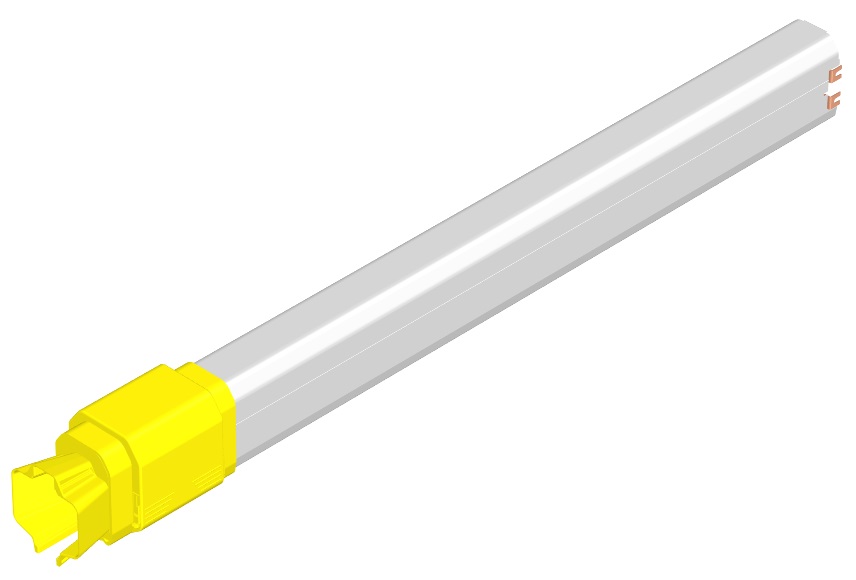
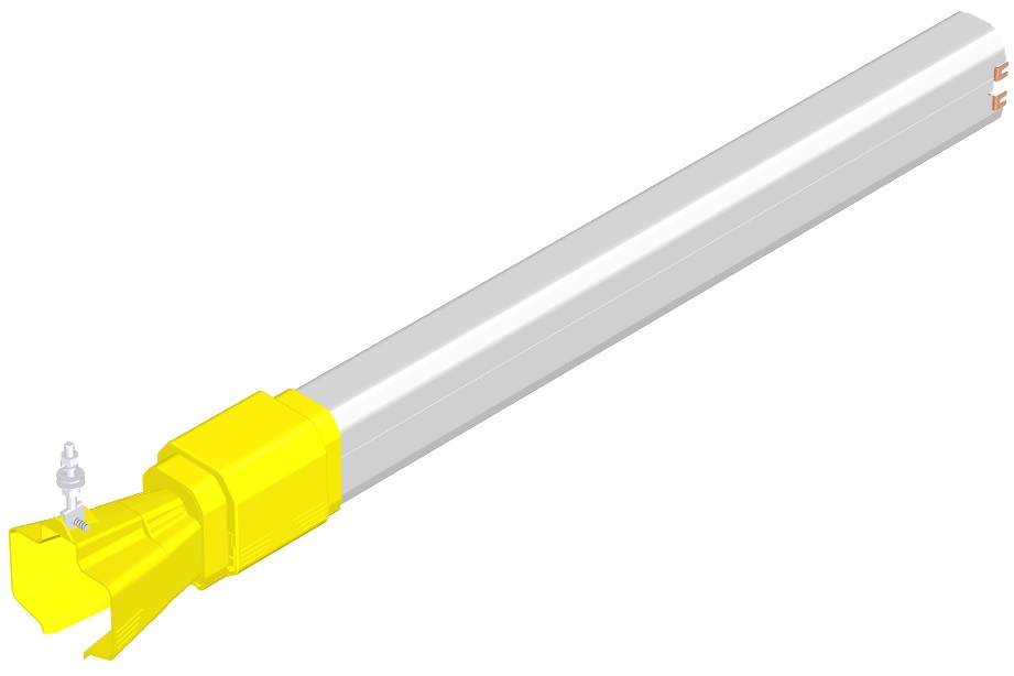
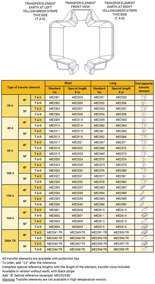
18 - Transfer elements (Transfer)
Ensures the passage of the trolley between discontinuous sections.
Advantages:
For feeding of switch or transfer systems
Allows to introduce the trolley without any intervention on the line
Description
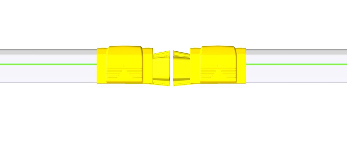
The purpose of the transfer elements is to ensure the trolley crosses over mechanically discontinuous line sections, for instance as in the case of switches. They can also be used for circuit interruptions (the advantage being that they actually cut the electrical circuit). However, transfer elements should in no case be used as electrical switches since they are not designed to resist electric arcing. Two types of transfer elements are offered: short transfer elements with short cones must be used when the facing cones are very close to each other with a minimum clearance of 10 mm and maximum clearance of 30 mm. Beyond that, use transfer elements with long cone. Safety: The contact with the protective earth conductor has priority over the other poles. The transfer element design does not allow access to the live parts, even from the front of the cone, due to the built-in insulators and safety distances. The transfer elements have a protection index of IP23 taking access to the dangerous parts into consideration, but do not offer any protection against solid foreign bodies (Ø12.5 ball test according to EN60529). Operator protection against access to the live brushes on the trolley and against the risk of mechanical blockages when crossing the interval between transfer elements must be provided by the customer. As the transfer elements are subjected to line expansion efforts, ME1500 fixed hangers must always be used together with rigid brackets such as ME1760 or ME1780, or welded brackets, for example. Furthermore, fixed hangers allow the transfer elements to withstand the stress caused by moving trolleys. The use of a special trolley for transfer element and/or of a special carrier for transfer element may be required, because of the dead length of the transfer elements and their geometry. Expansion joints can also be necessary beyond a certain distance between 2 transfer elements of the same line sector.
Product number and compatibilities
The transfer elements are pre-mounted on line elements. The total length is 1 metre in the standard version, but special lengths are available on request. A transfer element with the earth on the right is identified by facing the transfer guide, with the opening at the bottom, when the green-yellow band is located on the right, and inversely for the transfer element with earth on the left. A switch (or circuit interruption element) will always include a transfer element with the earth on the right and a transfer element with the earth on the left. Add the references for special lengths using the length of the element, with the transfer element included. Available in versions without earth conductor, line with black band. Add ‘- B’ after the reference (e.g. ME2525-B ). Caution! The transfer elements are not available in high temperature version. The following references are available:
Available with protection lips?
Yes
Available in high temperature variant?
No
Available without P.E.?
Yes
Available in curve version?
Yes
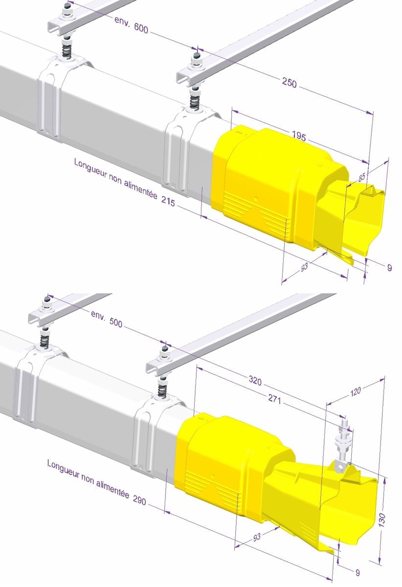
Technical data
Dead length: short transfer elements: 215mm, long transfer elements: 290mm. Weight: identical to the standard element of the same length. Index of protection IP23, as far as access to dangerous parts is concerned, but does not offer protection against ingress of foreign solid bodies (ball test Ø12.5 in conformance with EN60529). Travel speed in the transfers: maximum 70 m/min (beyond that, enquire)
Weight (kg)
Same as straight elements of the same length
Current rating
20A, 40A, 60A, 100A, 130A, 160A, 200A
Rated Voltage
750V
Rated Temperature
-20°C to +55°C
Material
Self-extinguishing PVC and thermoplastic, zinc coated steel screws and bolts
Mounting
Installation rules
Support each transfer element by 2 fixed hangers in accordance with the diagrams below.
Mounting rules
Align the transfer elements in both planes, within the limits of the following alignment tolerances: max. 3mm for short transfer elements and max. 10mm for long transfer elements. Adjust if need be to get the trolley run smoothly
Mounting required tools
Mounting required tools
Dismounting required tools
Maintenance
The operating life of the transfer elements and trolleys will be longer if the transfer elements are well aligned and if the trolleys are driven in the axis of the line. For a pair of transfer elements, the trolley should be replaced every 25,000 cycles through and back. After the same number of cycles, or at least once a year, you should check: – the degree of electrical insulation. If necessary clean the cone, after first disconnecting the installation from the mains. – the mechanical condition of the transfer elements and the trolleys (rollers, brushes, signs of wear in the cones etc.)
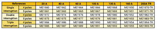
19 - Circuit interruption element (Standard)
Ensures the electrical insulation between 2 sections in the same feeding line.
Advantages:
Can be fitted as easily as a straight element
Visual location of the interruption position from the outside
Description
The purpose of the circuit interruption element is to insulate electrically one part of the line from another. Example: on a line with several travelling cranes, the circuit interruption element allows maintenance to be carried out on a crane (in a well defined area) while the other cranes continue to run. Selecting the type of circuit interruption element depends on how the line is used. – “safety” interruption: Prevents the insulation from being short-circuited via the trolley. This configuration requires the trolley to be driven manually or mechanically from one sector to the other over the insulation. The circuit interruption element must be adapted to the trolley type (e.g. double interruption for double collector trolley). – “comfort” interruption: In this case, it is possible to short-circuit the insulation via the trolley. This configuration means the trolley can pass automatically from one sector to the other with current continuity if a double or triple collector trolley is used. A single interruption is always appropriate for this configuration (it must be shorter than the trolley). Caution: The customer is responsible for taking the appropriate safety measures to prevent the trolley from short-circuiting the circuit interruption and supplying electricity to the maintenance area. Nota bene: The length “L” of the element should be stated when ordering. In the standard version, the interruption is located at the centre of the element, if you wish it to be placed elsewhere, please provide a drawing defining the position required. In this case, the element is given a special reference. For double or triple interruptions (no current continuity) the insulation area of 140 mm is extended. (412 mm for double interruptions and 684 mm for triple interruptions). The circuit interruption element must in no case be used as an electrical switch. The electrical arcs generated by driving the collector trolley across the interruption damage the conductors and insulators. Check possible reduction in the current capacity of the trolleys due to the insulators. Each section of the circuit must be provided with its own feed box. The earth conductor is continuous. The circuit interruption element is assembled like a standard element. When the maintenance area is cut off from the mains, make sure that no collector trolleys are travelling as they are likely to short-circuit the circuit interruption. The insulation between the conductors on the same pole on either side of the circuit interruption element must be checked regularly, at least once a year.
Product number and compatibilities
Available in standard range and with dust-protecting lips, add ‘- LV’ after the reference.
Available with protection lips?
Yes
Available in high temperature variant?
No
Available without P.E.?
Yes
Available in curve version?
No
Technical data
Weight (kg)
Identical to the equivalent standard element
Current rating
20A, 40A, 60A, 100A, 130A, 160A, 200A
Rated Voltage
750V
Rated Temperature
-30°C to +55°C
Material
Self-extinguishing PVC light grey
Mounting
Installation rules
Elements to be clipped in sliding hangers, connection of the elements end to end by tightening the connections.
Mounting rules
1. Insert the lines in the sliding hangers
2. Connect the lines
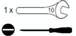
Mounting required tools
Mounting required tools
Maintenance
Regular inspection is required to check the insulation between the conductors of the same pole on both sides of the interruption, at least once a year.
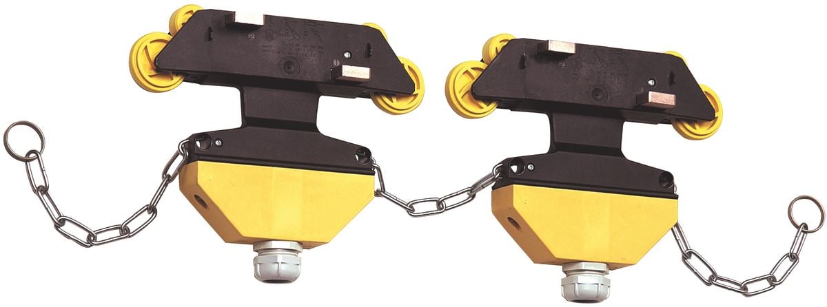
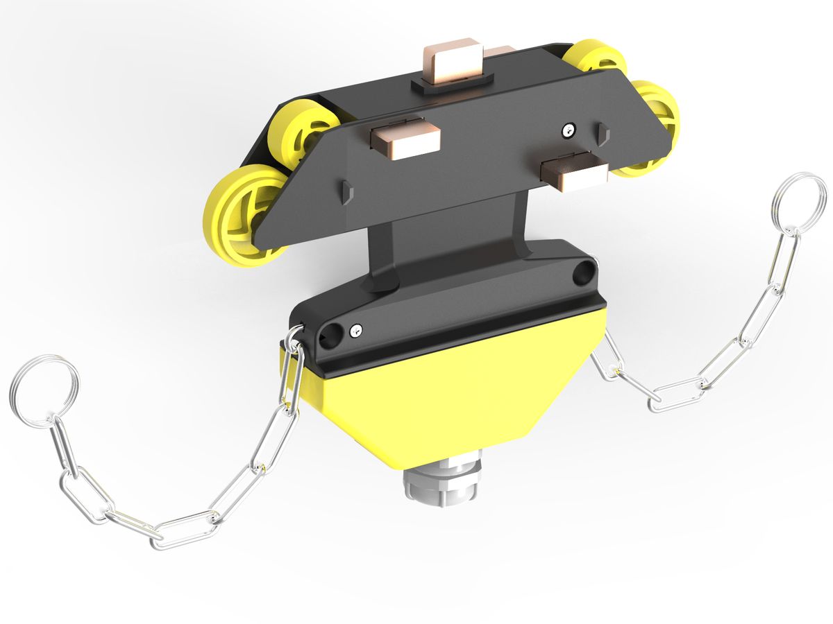
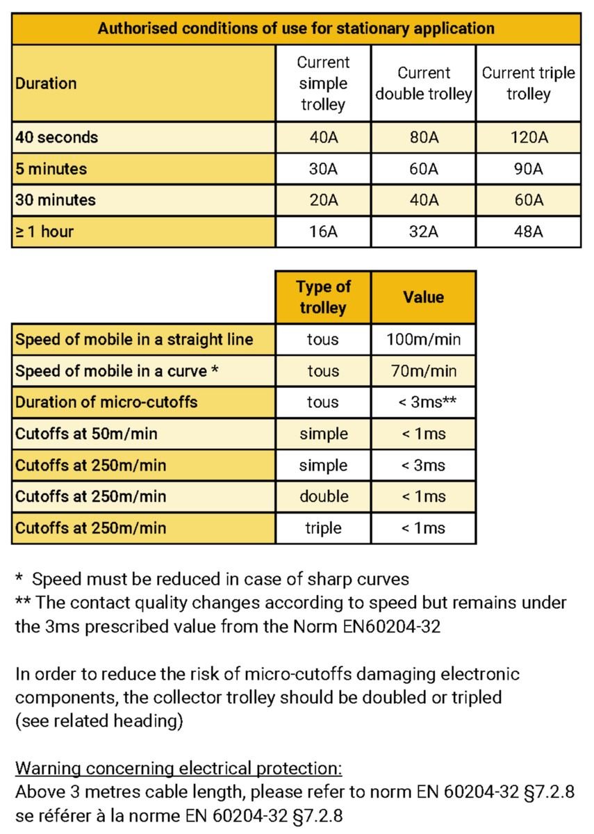
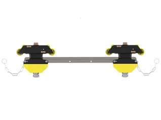
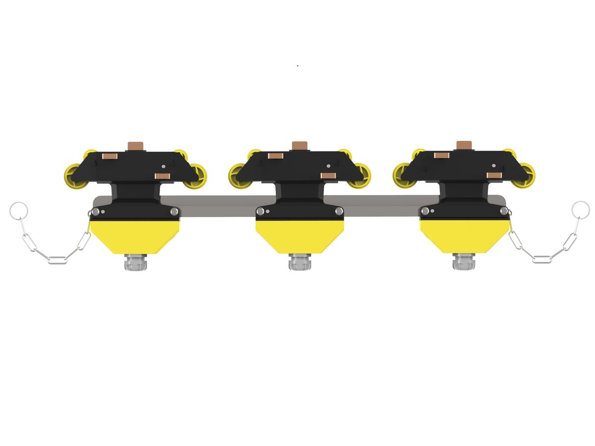
20 - Rigid trolleys (Standard)
The collector trolley shunts the electrical current in the Mobilis line to the mobile device requiring power.
Advantages:
Access to connection plate without taking trolley out
Available in version with/and without cable
Description
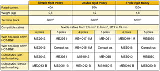
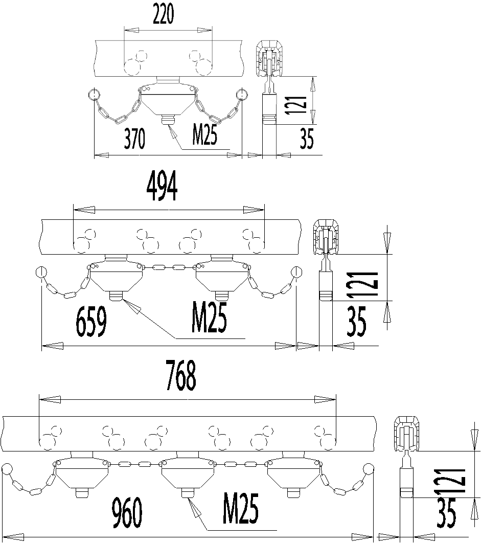
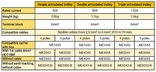
The rigid trolley is designed to shunt the electrical current in standard installations (no curve) operating at speeds up to 100m/min. It is not intended to support a load. It is inserted into the line by matching poles using a system of safety pins. The mechanical link between the trolley and the mobile device is ensured by the carrier. The self-lubricating carbon brushes, mounted on springs, thereby guaranteeing a permanent contact with the conductor. The trolley is available in 3 versions: – Two versions with a box, without cable, cable gland M25, allowing connection via flexible copper cables of 2.5 mm² to 6 mm², Ø13 to 19 mm, of Class 5 minimum only, one with a pole identified for earth (standard version), the other without earth location with poles L1 to L5. Third version prewired with earth pole, with cable H07-RNF (4 X 4 mm² or 5 X 4 mm² or 6 mm²). The prewired trolley can be delivered with a cable length of 1m (standard), or more (on request). The carbon brush (or brushes) are the parts of the Mobilis Elite trolley most subject to wear. They can be easily replaced without intervention on wiring. A simple screwdriver is all that is needed. The maximum wear tolerance is etched on the body of the trolley. The single trolley can shunt up to 40 A when travelling. For higher intensities, building a set of 2 to 3 collector trolleys (double collector, triple collector) can respectively shunt up to 80 A and up to 120 A. In installations with dust-protecting lips, only single trolleys should be used.

Product number and compatibilities
Rigid trolley up to 100m/min. For the simplified trolleys, high speed, articulated for curves, cleaners and special transfer, refer to the related items. For versions with box outlet without earth marking, add – B after the reference.
For versions with lateral exit, add -L after the reference.
For versions with enhanced force springs, add -RF after the reference.
Available without P.E. ?
Yes
Available in curve version?
see ‘articulated trolleys
Technical data
Cable diameter between 13.5mm and 17mm
Weight (kg)
According to reference
Carriage rating
40A, 80A, 120A
Rated Voltage
750V
Rated Temperature
-20°C to +75°C
Material
Self-extinguishing thermoplastic, self-lubricating carbon brushes, galvanised steel
Mounting
Installation rules
Providing an introduction gate allows to remove the trolley for maintenance, see the related section.
Mounting rules
Provide adequate loop of cable so as not to impede the motion of the trolley
Mounting required tools
Mounting required tools
Dismounting required tools
Maintenance
Check the wear of the brushes periodically using the wear indicator etched on the body of the trolley. The brushes can be replaced easily with no intervention on wiring required. A simple screwdriver only is necessary. An indicator showing the maximum wear tolerance is etched on the body of the trolley. Check the play and wear of the rollers.

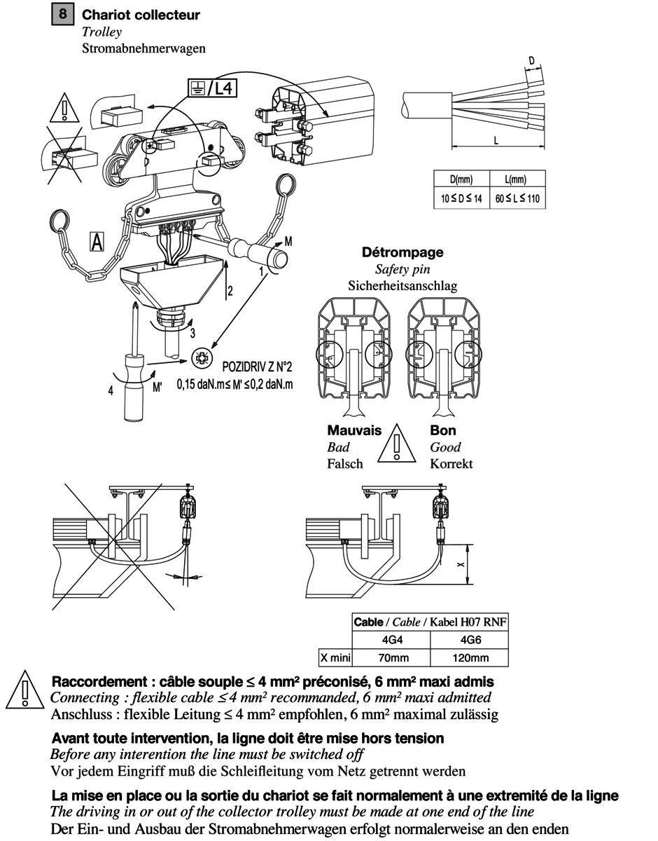
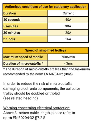
21 - Simplified trolleys (Standard)
The collector trolley shunts the electrical current in the Mobilis line to the mobile device requiring power.
Advantages:
Simplified version for low-intensity applications
Cost-effective up to max. 40A 4P
Description
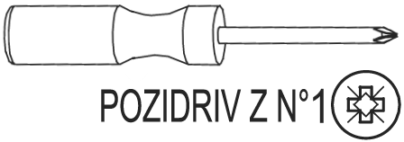
The simplified trolley is used to shunt the electrical current in standard installations (no curve) operating at speeds up to 70m/min of 4 poles maximum. It is not intended to support a load. It is inserted into the line by matching poles using a system of safety pins. The mechanical link between the trolley and the mobile device is ensured by the carrier. The self-lubricating carbon brushes, mounted on springs, thereby guaranteeing a permanent contact with the conductor. The trolley is available in 2 versions: – One version with a box, without cable, + cable gland M25, allowing connection via flexible copper cables of 2.5 mm² to 6 mm², Ø13 to 19 mm, of Class 5 minimum only. And a second version prewired with cable H07-RNF (4 X 4 mm² or 6 mm²). The prewired trolley can be delivered with a cable length of 1m (standard), or more (on request). The carbon brushes (or brushes) are the parts of the Mobilis Elite trolley most subject to wear. They can be easily replaced without intervention on wiring. A simple screwdriver is all that is needed. The maximum wear tolerance is etched on the body of the trolley. The single trolley can shunt up to 40 A when travelling. For higher intensities, use double or triple rigid collector trolleys.


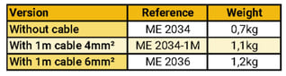
Product number and compatibilities
The simplified trolleys are available in versions fitted with/without cable HO7RNF.
Available in high temperature variant?
No
Available without P.E. ?
No
Available in curve version?
No
Technical data
Cable diameter between 13.5mm and 17mm
Overall dimensions
L (mm) : 29
H (mm) : 64
Z (mm) : 193
Weight (kg)
According to reference
Carriage rating
40A
Rated Voltage
750V
Rated Temperature
-20°C to +55°C
Material
Self-extinguishing thermoplastic, self-lubricating carbon brushes, galvanized steel
Mounting
Installation rules
Providing an introduction gate allows to remove the trolley for maintenance, see the related section.
Mounting rules
Provide adequate loop of cable so as not to impede the motion of the trolley.
Mounting required tools
Mounting required tools
Dismounting required tools
Maintenance
Check the wear of the brushes and the general state of the trolley periodically.
22 - Articulated trolley (Curves)
The articulated trolley is for installations with horizontal curves (whatever the radius).
Advantages:
Suitable for installations with curves
Access to connection plate without taking trolley out
Description
Articulated trolley must be used to shunt the electrical current in all installations including curves with maximum speed limit of 70m/min. They are not intended to support a load. An articulated trolley is inserted into the line by matching poles using a system of safety pins. The mechanical link between the trolley and the mobile device is ensured by the carrier. The self-lubricating carbon brushes, are mounted on springs, thereby guaranteeing a permanent contact with the conductor. The trolley is available in in 3 versions: – Two versions with a box, without cable, + cable gland M25, allowing connection via flexible copper cables of 2.5 mm² to 6 mm², Ø13 to 19 mm, of Class 5 minimum only, one with a pole identified for earth (standard version), the other without earth location with poles L1 to L5. Third version prewired with earth pole, with cable H07-RNF (4 X 4 mm² or 5 X 4 mm² or 6 mm²). The prewired trolley can be delivered with a cable length of 1m (standard), or more (on request). The carbon brush (or brushes) are the parts of the Mobilis Elite trolley most subject to wear. They can be easily replaced without intervention on wiring. A simple screwdriver is all that is needed. The maximum wear tolerance is etched on the body of the trolley. The single trolley can shunt up to 40 A when travelling. For higher intensities, building a set of 2 to 3 collector trolleys (double collector, triple collector) can respectively shunt up to 80 A and up to 120 A. In installations with dust-protecting lips, only single trolleys should be used.

Product number and compatibilities
Trolley references for installation with horizontal curve according to the following table.
Available without P.E.?
Yes
Available in curve version?
Yes
Technical data
Overall dimensions
L (mm) : 35
Z (mm) : 251
Weight (kg)
According to reference
Carriage rating
40A, 80A, 120A
Rated Voltage
750V
Rated Temperature
-20°C to +75°C
Material
Self-extinguishing thermoplastic, self-lubricating carbon brushes
Mounting
Installation rules
For satisfactory operation, check the position of the trolleys when carried in the curved sections, including when the position of the current taker is shifted in relation to the mobile device, and limit offsetting to a maximum of 50mm
Mounting rules
Adjust the position of the trainer to cross over junctions smoothly.
.png?width=318&name=inst017_zoom%20(1).png)
Mounting required tools
Mounting required tools

Dismounting required tools
Maintenance
Check the wear of the brushes periodically using the wear indicator etched on the body of the trolley. The brushes can be replaced easily with no intervention on wiring required. A simple screwdriver only is necessary. An indicator showing the maximum wear tolerance is etched on the body of the trolley. Check the play and the wear of the rollers.
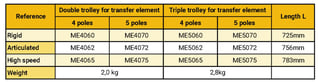
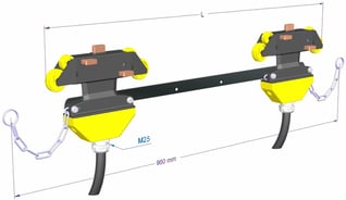
23 - Special trolley for transfer element (Transfer)
To ensure continuity of electrical supply in the transfers and guiding of trolley for crossing transfer elements.
Advantages:
Current continuity in the transfers with short transfer elements
Suitable for transfers
Description
Caution: Operator protection against access to the live brushes on the trolley when crossing the clearance between transfer elements must be provided by the customer. The dead length, made up of the cones of the transfer elements and the insulators, requires the use of sets of specially designed trolleys and carriers. Trolley for short transfer element: With transfer elements with a short cone, double or triple trolleys with a coupling bar should be used together with a triple carrier with box type ME1650 (4 poles) or ME1655 (5 poles) to ensure current continuity. Trolley for long transfer element: Use standard single trolleys (rigid or articulated as appropriate) and double and triple coupled trolleys. In the clearance between the transfer elements, the trolleys must be maintained in the air. It is imperative to use a special carrier reference ME1680. In the standard version, cable 1 metre long only. The special trolley for transfer element is used to shunt the electrical current in installations with short or long transfer elements. The max. speed when crossing the transfer elements is 70m/min. Apart from the transfer elements, speed up to 100m/min with rigid or articulated trolleys, 180m/min with high speed trolleys. The special trolley for transfer element is not intended to support a load. It is inserted into the line by matching poles using a system of safety pins. The mechanical link between the trolley and the mobile device is ensured by the carrier. The self-lubricating carbon brushes, are mounted on springs, thereby guaranteeing a permanent contact with the conductor. The carbon brush (or brushes) are the parts of the Mobilis Elite trolley most subject to wear. They can be easily replaced without intervention on wiring. A simple screwdriver is all that is needed. The maximum wear tolerance is etched on the body of the trolley. The single trolley can shunt up to 40 A when travelling. For higher intensities, building a set of 2 to 3 collector trolleys (double collector, triple collector) can respectively shunt up to 80 A and up to 120 A.
Product number and compatibilities
The following references apply to the trolleys for transfer with 1-metre cable outlet.
Available without P.E.?
Yes
Available in curve version?
Yes
Technical data
Feeding is continuous in the case of transfer between short transfer elements with maximum space between them of 30mm, and discontinuous in other cases. Please refer to the section on transfer elements to learn about the dead lengths.
Overall dimensions
L (mm) : 35
H (mm) : 121
Z (mm) : 960
Weight (kg)
According to reference
Carriage rating
Trolleys 80A, 120A, with reduced intensity in transfert up to 40A
Rated Voltage
750V
Rated Temperature
-30°C to +75°C
Material
Self-extinguishing thermoplastic, self-lubricating carbon brushes, galvanised steel
Mounting
Installation rules
To be used imperatively with transfer elements, or if double or triple trolleys are needed with long transfer elements
Mounting rules
1. Clip-on the trolley in the line following the direction of the earth pole.
2. Associate the trolley to the trainer.
3. Make sure the transfer elements are well aligned before any translation motion occurs.
4. Make sure there is no excessive mechanical tension due to the adjustment of the carrier or to the traction of the cables
Mounting required tools
Mounting required tools
Dismounting required tools
Maintenance
Check the wear of the brushes periodically using the wear indicator etched on the body of the trolley. The brushes can be replaced easily with no intervention on wiring required. A simple screwdriver only is necessary. An indicator showing the maximum wear tolerance is etched on the body of the trolley. Check the play and the wear of the rollers.
24 - High speed trolley (Standard)
The high speed trolley shunts the electrical current in the Mobilis line to the mobile device requiring power for speeds > 100m/min.
Advantages:
Suitable for speeds up to 180m/min
Quality of contact preserved at high speed
Description
High speed trolleys have extra rollers to cross over junctions smoothly, even when travelling at high speeds or in very cold weather conditions. High speed trolleys are required for speeds greater than 100 m/min. It is strongly recommended for temperatures below -20°C. All other features of high speed trolleys (excepting running speed and overall dimensions) are identical to those of the rigid trolleys. Version without cable allowing connection via flexible copper cables of 2.5 mm² to 6 mm², Ø13 to 19 mm, of Class 5 minimum only. Notice: the triple high speed trolleys are not compatible with the triple carriers. Build a specific carrier or combine single and/or double trolleys with simple and/or double carriers.

Product number and compatibilities
References: All high speed trolleys are supplied without cable, please refer to the following list of references.
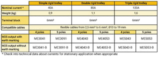
Available without P.E.?
Yes
Available in curve version?
No
Technical data
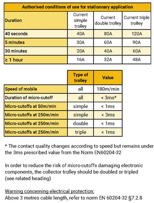
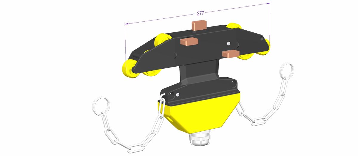
Overall dimensions
L (mm) : 35
Z (mm) : 277
Weight (kg)
1 kg
Carriage rating
40A, 80A, 120A
Rated Voltage
750V
Rated Temperature
-30°C to +75°C
Material
Self-extinguishing thermoplastic, self-lubricating carbon brushes, galvanized steel
Mounting
Installation rules
Providing an introduction gate allows to take out the trolley for maintenance, see the related section. The triple high speed trolleys are not compatible with the triple carriers, use a double carrier and a simple carrier.
Mounting rules
Provide adequate loop of cable so as not to impede the motion of the trolley
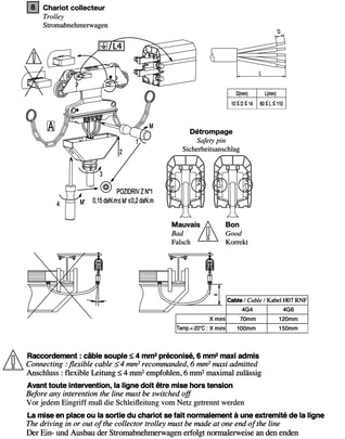
Mounting required tools
Mounting required tools
Dismounting required tools
Maintenance
Check the wear of the brushes periodically using the wear indicator etched on the body of the trolley. The brushes can be replaced easily with no intervention on wiring required. A simple screwdriver only is necessary. An indicator showing the maximum wear tolerance is etched on the body of the trolley. Check the play and the wear of the rollers.
26 - Standard carrier (Standard)
Element of mechanical link connection between the collector trolley and the mobile device requiring power.
Advantages:
Large clearance
For driving squares 20 to 50mm
Description
The standard carriers ensure the mechanical link between the collector trolley which travels inside the Mobilis Elite line and the mobile device requiring current. The triple carriers are not compatible with the triple high speed trolleys.
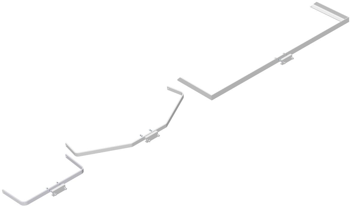
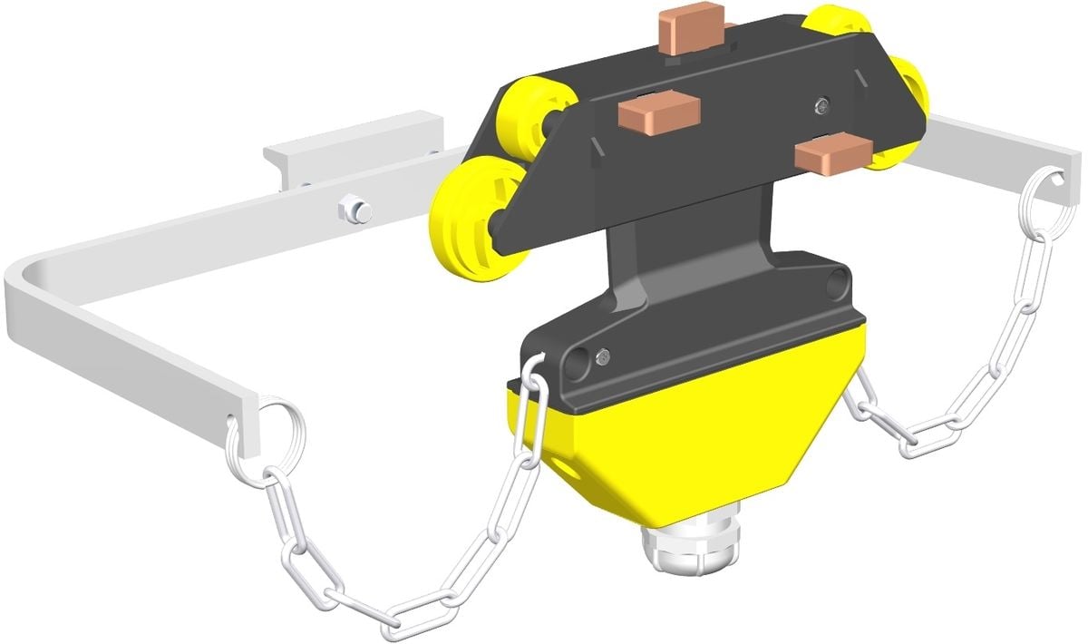
Product number and compatibilities
The references are as follows:
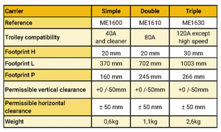
Available with protection lips?
Simple carrier compatible
Available in curve version?
Compatible
Technical data
See references

Weight (kg)
According to reference
Rated Temperature
-30°C to +75°C
Material
Zinc coated steel
Mounting
Installation rules
Check that the space required for the carrier is available all along the line.
Mounting rules
Adjust in the vertical plane to have the chain of traction of the trolley horizontal or tended downwards (max. -50mm). In the horizontal plane, the chain of the trolley must be in the axis of the line +/- 50mm. Correct adjustment increases the operating life of the trolley collector.
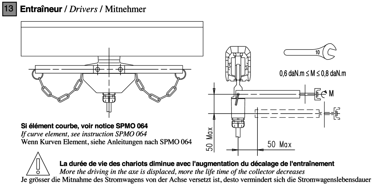
Mounting required tools
Mounting required tools

Dismounting required tools
Maintenance
This element does not require any special maintenance.
27 - Carrier with box (Standard)
Element of mechanical link and electrical connection between the collector trolley and the mobile device requiring power.
Advantages:
Box with intermediate terminal between the trolleys and the mobile device requiring power
For driving squares 20 to 50mm
Description
The carriers with box ensure the mechanical link between the collector trolley which travels inside the Mobilis Elite line and the mobile device requiring current. They also provide an intermediary connection point between the collector(s) carried and the supply cable of the mobile device.
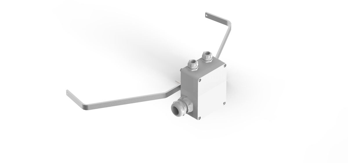
Product number and compatibilities
The following references related to the carriers usually supplied according to the trolleys to be carried. The triple carrier with box is not suitable for currents above 100A.
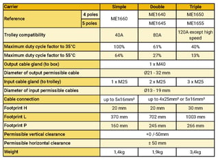
Available with protection lips?
Simple carrier compatible
Available without P.E. ?
Compatible
Available in curve version?
Compatible
Technical data
See references
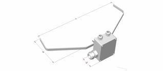
Weight (kg)
According to reference
Rated Voltage
750V
Rated Temperature
-30°C to +60°C
Material
Zinc coated steel and ABS
Mounting
Installation rules
Check that the space required for the carrier is available all along the line.
Mounting rules
Adjust in the vertical plane to have the chain of traction of the trolley horizontal or tended downwards (max. -50mm). In the horizontal plane, the chain of the trolley must be in the axis of the line +/- 50mm. Correct adjustment increases the operating life of the trolley collector.
Mounting required tools
Mounting required tools
Dismounting required tools
Maintenance
This element does not require any special maintenance.
28 - Special carrier for long transfer element (Transfer)
Maintains the trolley in the air during the interval between long transfer elements.
Advantages:
Supports the trolley outside of the line
Unique model for single, double or triple trolleys for special transfer elements
Description
Whenever space between the transfer elements is greater than 30mm, the use of long transfer elements and this special carrier is required: it maintains the trolley in the air (simple, double or triple) in the clearance between the long transfer elements. It is useless when short transfer elements with a space less than 30mm are used.
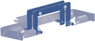
Product number and compatibilities
ME1680
Available with protection lips?
Compatible
Available in curve version?
Compatible
Technical data
Assembling on square of 30 to 50mm, permitted horizontal clearance: +/-12mm, permitted vertical clearance: +/-15mm
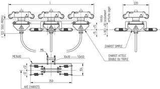
Weight (kg)
1,2 kg
Rated Temperature
-30°C to +75°C
Material
Zinc coated steel, aluminium
Mounting
Installation rules
Check that the space required for the carrier is available all along the line.
Mounting rules
Adjust the carrier so that the trolley enters the transfer elements smoothly. Position the cables of the trolleys to limit the parasitic efforts. Limit traction on the springs as much as possible for one maximum operating life of the trolleys.
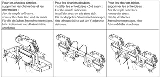
Mounting required tools
Mounting required tools
Dismounting required tools
Maintenance
This element does not require any special maintenance.
29 - Special carrier for long transfer element (Transfer)
End of travel electro-mechanical link stop.
Advantages:
Position can be changed easily
Easy fit on the Mobilis line
Description
Located on one element of the line, it allows the overhead travelling crane provided with a cross-type sensor limit switch to detect a position or the end of line with no other elements required to be fitted to the structure.
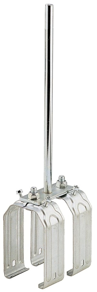
Product number and compatibilities
ME1550
Available with protection lips?
Compatible
Available in curve version?
Compatible
Technical data
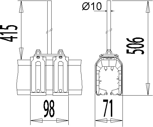
Overall dimensions
L (mm) : 71
H (mm) : 506
Z (mm) : 98
Weight (kg)
0,57 kg
Rated Temperature
-30°C to +75°C
Material
Zinc coated steel
Mounting
Installation rules
To be positioned normally at each end of the line. Provide suitable space to allow the travelling crane to stop at full speed.
Mounting required tools
Mounting required tools

Dismounting required tools
Maintenance
This element does not require any special maintenance.
30 - Set of 5 screws + nuts 20A – 100A (Accessories)
Advantages:
Description
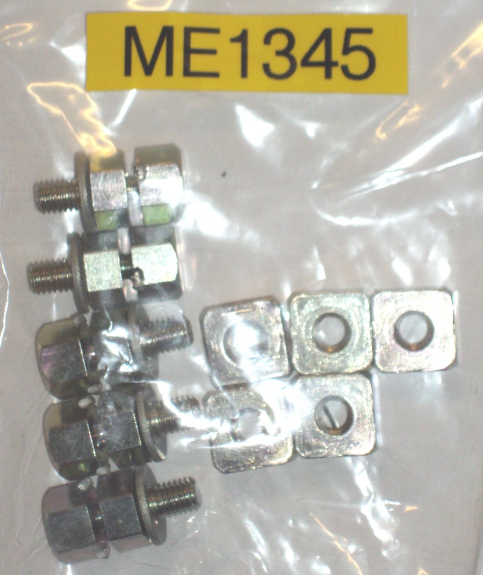
Product number and compatibilities
ME1345
Mounting required tools
31 - Set of feed connection for 5th pole (Accessories)
Advantages:
Description
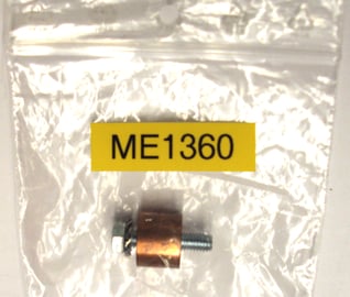
Product number and compatibilities
ME1360
Mounting required tools
32 - Set of 10 screws + 5 nuts 130A (Accessories)
Replacement connection screws and nuts for 1 element 130A 5 poles.
Advantages:
Description
Product number and compatibilities
ME1357
Mounting required tools
33 - Set of connection screws 160A (Accessories)
Replacement connection part for 1 element 160A 5 poles.
Advantages:
Description
Product number and compatibilities
ME1353
Mounting required tools
34 - Set of connections for 200A 5 poles (Accessories)
Replacement connection part for 1 element 200A 5 poles.
Advantages:
Description
Product number and compatibilities
For elements 200A: ME1358, For 200A-TR elements: ME1358-TR
Mounting required tools
35 - Set of connection screws 200A (Accessories)
Replacement connection screws for phase and earth conductors on element 200A 5 poles.
Advantages:
Description
Product number and compatibilities
For elements 200A: ME1352, For 200A-TR elements: ME1352-TR
Mounting required tools
36 - Set of 4 collector brushes (Accessories)
Replacement brushes for single 4-pole trolley type ME3043 and derivatives.
Advantages:
Description

Product number and compatibilities
ME1354
Mounting required tools
37 - Set of 5 collector brushes (Accessories)
Replacement brushes for single 5-pole trolley type ME3051 and derivatives
Advantages:
Description

Product number and compatibilities
ME1355
Mounting required tools
38 - Brush for simplified trolley (Accessories)
Replacement brush for simplified trolley type ME2034.
Advantages:
Description
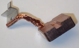
Product number and compatibilities
ME0306
Mounting required tools
39 - Set of 5 cleaning brushes (Accessories)
Replacement brushes for single 5-pole cleaning trolley type ME4525 and derivative.
Advantages:
Description

Product number and compatibilities
ME1356
Mounting required tools
40 - Set of 2 special screws for fixed hangers (Accessories)
Converts a sliding hanger into a fixed hanger.
Advantages:
Description
Product number and compatibilities
ME1501
Mounting required tools
41 - Set of 2 carrier rings (Accessories)
Replacement rings linking the chains of the trolley to the carrier.
Advantages:
Description
Product number and compatibilities
ME1359
Mounting required tools
42 - Cone for short transfer element (Accessories)
Replacement cone for short transfer element.
Advantages:
Description
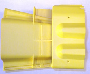
Product number and compatibilities
ME0188
Mounting
Mounting rules
Cut off mains voltage to the line. Remove the covering flange of transfer element using a flat screwdriver. Replace the cone making sure to insert all guiding studs of and the cone fully, remove the bridge maintaining the wings of the cone. Put back on the covering flange of transfer element.
Mounting required tools
42 - Cone for short transfer element (Accessories)
Replacement cone for short transfer element.
Advantages:
Description
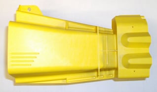
Product number and compatibilities
ME0189
Mounting
Mounting rules
Cut off mains voltage to the line. Remove the covering flange of transfer element using a flat screwdriver. Replace the cone making sure to insert all guiding studs of and the cone fully, remove the bridge maintaining the wings of the cone. Put back on the covering flange of transfer element.
Mounting required tools
Downloads
Mobilis Elite Assembly instructions:
Catalogue
Mobilis Elite in our catalogue (PDF)
2D File Package for CAO in DXF format
3D File Package for CAO in STEP format
3D File Package for CAO in IGS format
To open the File Packages in format 7Zip, if your usual compression doesn’t take 7z file in charge, you will have to download 7Zip on www.7zip.org (since you have uncompressed the file click on 7zFM.exe and open the CAO downloaded file and click on “Open…”)